Sensing optical fiber unit structure for pipeline risk monitoring and early warning and construction method

A technology for sensing optical fiber and risk monitoring, which is applied in the use of optical devices to transmit sensing components, fiber mechanical structures, optical components, etc. question

Pending Publication Date: 2021-06-18
北京百世通管道科技有限公司
View PDF5 Cites 0 Cited by
  • Summary
  • Abstract
  • Description
  • Claims
  • Application Information

AI Technical Summary

Problems solved by technology

[0003] First, the pipeline construction window is very short. Once the pipeline is buried underground, it will be impossible to excavate and expose the pipeline to lay distributed optical fiber sensors across the line.
The design service life of the pipeline is more than 50 years, and some pipelines have a design life of 100 years. If there is no solution for laying and replacing the sensing optical fiber, once the pipeline is buried, due to the long pipeline, coupled with construction costs, environment along the way, Due to the influence of roads and buildings, it will be impossible to excavate and re-lay the sensing optical fiber unit throughout the pipeline life cycle, and pipeline monitoring will not be possible
[0004] Second, the traditional construction method leads to many optical fiber joints and increases loss, which not only affects the monitoring distance and effect, but also increases the cost
In the actual construction process, in order to meet the construction period requirements of different regions, the construction unit will construct at the same time in sections or skip and discontinuously construct the same section of pipeline; in addition, due to land acquisition, road traffic, weather, terrain and other factors, it is impossible to start according to the pipeline If the pipeline is installed from the beginning to the end in the initial order, the sensing fiber cannot be laid according to the established order and length of the coil, which will cause the fiber to be cut into many sections and then be forced to increase the fiber connector, resulting in an increase in the loss of the fiber connector; When laying the sensing optical fiber, if the pipeline leakage is found during the pressure test after the pipeline trench is backfilled, it is necessary to use a large-scale mechanical excavation to repair or replace the pipe joint again, which will cause the sensing optical cable to be cut off, and an additional optical cable will be added for a breakpoint and 2 fiber optic connectors
If the connector loss increases too much, it will lead to an increase in the fiber loss in the whole process, which will seriously affect the monitoring distance and quality of the fiber optic sensing system, and increase the project cost; the number of fiber connectors is too large to a certain extent, and even cause the fiber sensor system to lose too much and unable to work;
[0005] Third, the buried sensing fiber cannot be replaced after its lifespan expires
If the countermeasures for replacing the sensing optical fiber are not considered early, the large-scale promotion of directly buried sensing optical fiber will cause serious consequences and immeasurable economic losses due to the failure of the pipeline risk monitoring and early warning system in the later stage.

Method used


Image

  • Sensing optical fiber unit structure for pipeline risk monitoring and early warning and construction method
  • Sensing optical fiber unit structure for pipeline risk monitoring and early warning and construction method
  • Sensing optical fiber unit structure for pipeline risk monitoring and early warning and construction method

Examples


Embodiment Construction

[0030] The technical solution of the present invention will be described in detail below in conjunction with the accompanying drawings and specific embodiments.

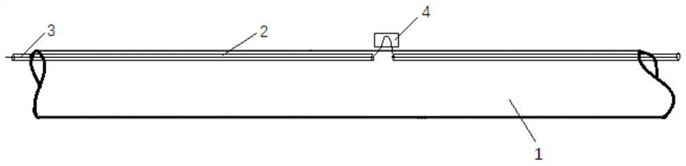
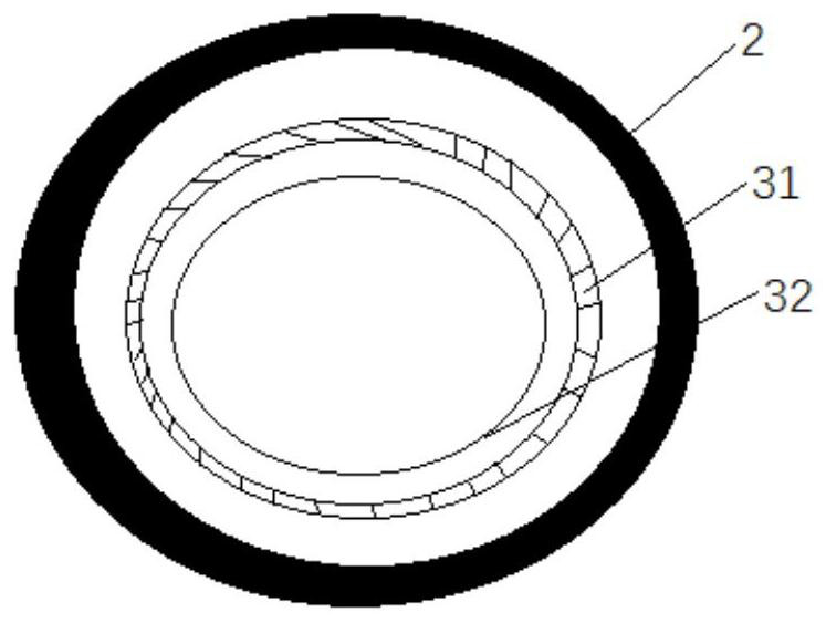
[0031] like Figure 1-2As shown, a sensing fiber unit structure for pipeline risk monitoring and early warning in this embodiment is composed of a microtube 2 protecting the sensing fiber unit 3 and a sensing fiber unit 3 . The micropipes 2 are formed by a plurality of micropipes 2 sealed from end to end, and can be quickly and synchronously laid on the outer wall of the medium conveying pipeline 1 within a limited window period during the construction of the medium conveying pipeline 1. The micropipes can be laid according to It is necessary to cut off and connect at any time and place to avoid various contradictions and mutual interference between the construction of the medium conveying pipeline 1 and the construction of the microtube 2, and save the construction period; and to avoid or reduce the connection of th...


PUM


Abstract

The invention discloses a sensing optical fiber unit structure for pipeline risk monitoring and early warning and a construction method. During pipeline construction, a micro-pipe is laid on the outer wall of a pipeline synchronously, and after the pipeline is completely completed or a pipeline monitoring and early warning system needs to be built in the future, a sensing optical fiber unit can be laid in the micro-pipe under the non-excavation condition, wherein the sensing optical fiber unit comprises a sensing optical fiber for monitoring real-time state data of the pipeline, and the real-time state data comprises temperature, vibration and strain; or after the sensing optical fiber breaks down or the service life is due, a new sensing optical fiber unit can be replaced without excavation. The practical problems that many sensing optical cables which are directly buried along with pipelines and used for monitoring and early warning are large in construction difficulty, multiple in joints and large in loss can be solved, and more importantly, the problem that fault points need to be excavated and found when the directly-buried sensing optical cables break down in a traditional method is solved. More importantly, the problem that the sensing optical cable cannot be replaced when the optical cable is not excavated in the whole line due to the life cycle in the future is solved.

Description

technical field [0001] The invention relates to a structure and construction method of a sensing optical fiber unit for pipeline risk monitoring that is convenient for the laying and replacement of sensing optical fibers, and is suitable for the construction and replacement of sensing optical fiber units for buried pipelines in industries such as heating, water supply, oil and gas, and chemical industry. Background technique [0002] Pipeline is a convenient, efficient and cost-effective transportation device, and it is an important infrastructure to ensure the national economy and people's livelihood. In recent years, major domestic and international serious pipeline accidents have caused heavy losses, and the number of road subsidences caused by pipeline leakage is increasing day by day. It has become a top priority to build digital and intelligent pipelines and grasp the status data of the entire pipeline in real time. Installing optical fiber distributed optical fiber se...

Claims


Application Information

Patent Timeline
Patent Type & Authority Applications(China)
IPC IPC(8): G02B6/44G02B6/50G01D5/353
CPCG02B6/4459G02B6/50G01D5/3538
Inventor 缪宏周抗冰缪文韬戴荣荣
Owner 北京百世通管道科技有限公司
Why Eureka
Try Eureka