Configuration method, terminal and network side device

A technology of network side equipment and configuration method, applied in the directions of pilot signal allocation, transmission path sub-channel allocation, digital transmission system, etc., can solve the problem of inability to meet the feedback requirements of large-capacity and low-latency uplink channels, and reduce uplink Overhead, the effect of reducing feedback delay

Pending Publication Date: 2021-06-18
CHINA MOBILE COMM LTD RES INST +1
View PDF8 Cites 0 Cited by
  • Summary
  • Abstract
  • Description
  • Claims
  • Application Information

AI Technical Summary

Problems solved by technology

[0003] In view of this, the present invention provides a configuration method, terminal and network-side equipment, which are used to solve the problem that the current reference signal configuration for channel detection cannot meet the needs of large-capacity and low-latency uplink channel feedback

Method used


Image

  • Configuration method, terminal and network side device
  • Configuration method, terminal and network side device
  • Configuration method, terminal and network side device

Examples


Embodiment Construction

[0082] In order to make the purpose, technical solutions and advantages of the embodiments of the present invention more clear, the following will clearly and completely describe the technical solutions of the embodiments of the present invention in conjunction with the drawings of the embodiments of the present invention. Apparently, the described embodiments are some, not all, embodiments of the present invention. All other embodiments obtained by those skilled in the art based on the described embodiments of the present invention belong to the protection scope of the present invention.

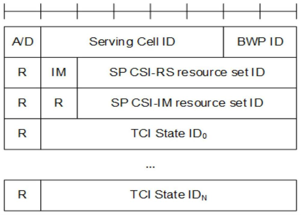
[0083] In related technologies, the downlink reference signal and the traffic channel can be configured with a quasi co-location (Quasi Co-Location, QCL) relationship, and the configuration process is as follows:

[0084] 1. The higher layer configures the QCL through the Transmission Configuration Indicator (TCI) state (TCI-State), and the parameters of the TCI-State are used in one or two...


PUM


Abstract

The present invention provides a configuration method, a terminal and a network side device, belonging to the technical field of wireless communications, the configuration method applied to the network side device comprising the steps of: issuing configuration information, the configuration information being used for indicating an association relationship between a reference signal for channel detection and a downlink reference signal. In the invention, the terminals with the same association relationship adopt the same SRS resource, so that the feedback time delay can be reduced and the uplink overhead can be reduced in a high-capacity scene (such as a high-speed rail).

Description

technical field [0001] The present invention relates to the technical field of wireless communication, in particular to a configuration method, a terminal and a network side device. Background technique [0002] The existing uplink reference signal—Sounding Reference Signal (SRS) configuration for channel sounding cannot meet the requirements of large-capacity and low-latency scenarios, such as high-speed rail scenarios. Specifically, each symbol (symbol) of the existing SRS can only have a maximum capacity of 4*12, a total of 48 terminals, and 3 uplink time slots in a 5ms subframe. If two symbols per uplink time slot are used for 4 antennas to send SRS in turn, then A maximum of 72 terminals can be accommodated in a 5ms subframe. According to the simulation results, the maximum cyclic shift (CS) is set to 2 in high-speed scenarios, otherwise intersymbol interference will occur. That is, a maximum of 12 terminals can be accommodated in a 5ms subframe, and the uplink overhe...

Claims


Application Information

Patent Timeline
Patent Type & Authority Applications(China)
IPC IPC(8): H04L5/00
CPCH04L5/0094H04L5/0048H04L5/005
Inventor 周娇徐晓东童辉刘建华陈卓
Owner CHINA MOBILE COMM LTD RES INST
Why Eureka
Try Eureka