
RFID intelligent equipment cabinet

A technology of intelligent equipment and auxiliary cabinets, applied in the direction of cooperative operation devices, instrument-controlled coin-operated equipment, coin-operated equipment for distributing discrete items, etc., can solve the problem of small number of equipment, low intelligence of storage rooms, Problems such as equipment storage confusion, to reduce time-consuming, ensure processing efficiency, and improve work efficiency

Pending Publication Date: 2021-06-22
ZHEJIANG JUNMP TECH
View PDF0 Cites 0 Cited by
  • Summary
  • Abstract
  • Description
  • Claims
  • Application Information

AI Technical Summary

Problems solved by technology

[0007] The purpose of the present invention is to provide an RFID intelligent equipment cabinet to solve the problem in the above background technology that the traditional equipment storage room has a low degree of intelligence and cannot individually mark each piece of equipment in the cabinet, resulting in very confusing storage of equipment , and there is no corresponding restriction on the use and storage of equipment, resulting in the staff not returning the equipment in time after use, resulting in the phenomenon of empty cabinets, and due to the limitation of its own space, the number of equipment stored is small , the problem of being unable to adapt to the diversified needs of medium and large factories

Method used


Image

  • RFID intelligent equipment cabinet
  • RFID intelligent equipment cabinet
  • RFID intelligent equipment cabinet

Examples


Embodiment 1

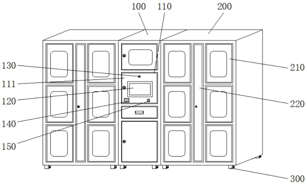
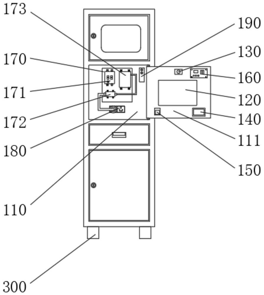
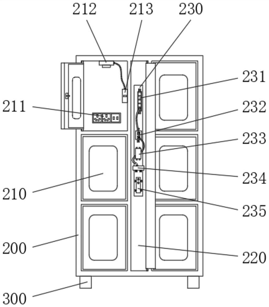
[0033] See Figure 1-3 with Figure 7-8The present invention provides a technical solution: an RFID intelligent equipment cabinet, including a host 100, at least one sub-cabinet 200, can be configured on the left or right side of the main cabinet, and the number of securing the number can be based on the application The side or right side is increased in series, and the control chamber 110 is fixed at the center of the front side wall of the main cabinet 100, and the connection end of the control chamber 110 rotates to connect the door body 111, and the front side wall of the door body 111 is inlaid. Touch display Screen 120, the front side wall of the door body 111 and the upper side of the touch display screen 120 inlaid, the face recognition camera 130, the lower side of the front side wall of the door body 111 and the left side of the touch screen 120 with speaker 140, door body The front side wall of 111 and the right side of the touch screen 120 is inlaid, the rear side wall o...

Embodiment 2

[0036] See Figure 1-3 , Figure 6 with Figure 8 The present invention provides a technical solution: an RFID intelligent equipment cabinet, including a host 100, at least one sub-cabinet 200, can be configured on the left or right side of the main cabinet, and the number of securing the number can be based on the application The side or right side is increased in series, and the control chamber 110 is fixed at the center of the front side wall of the main cabinet 100, and the connection end of the control chamber 110 rotates to connect the door body 111, and the front side wall of the door body 111 is inlaid. Touch display Screen 120, the front side wall of the door body 111 and the upper side of the touch display screen 120 inlaid, the face recognition camera 130, the lower side of the front side wall of the door body 111 and the left side of the touch screen 120 with speaker 140, door body The front side wall of 111 and the right side of the touch screen 120 is inlaid, the rear s...

Embodiment 3

[0039] See Figure 1-5 with Figure 8-9The present invention provides a technical solution: an RFID intelligent equipment cabinet, including a host 100, at least one sub-cabinet 200, can be configured on the left or right side of the main cabinet, and the number of securing the number can be based on the application The side or right side is increased in series, and the control chamber 110 is fixed at the center of the front side wall of the main cabinet 100, and the connection end of the control chamber 110 rotates to connect the door body 111, and the front side wall of the door body 111 is inlaid. Touch display Screen 120, the front side wall of the door body 111 and the upper side of the touch display screen 120 inlaid, the face recognition camera 130, the lower side of the front side wall of the door body 111 and the left side of the touch screen 120 with speaker 140, door body The front side wall of 111 and the right side of the touch screen 120 is inlaid, the rear side wall o...


PUM


Abstract

The invention discloses an RFID intelligent equipment cabinet in the technical field of equipment storage equipment. The cabinet comprises a main cabinet body and at least one auxiliary cabinet body; the auxiliary cabinet bodies can be arranged on the left side or the right side of the main cabinet body, and the number of the auxiliary cabinet bodies can be increased in series on the left side or the right side according to application conditions; the RFID intelligent equipment cabinet is reasonable in structural design, the ultrahigh frequency RFID technology is combined with a traditional equipment storage chamber, the time consumed for finding equipment in actual use is shortened, the equipment storage chamber is convenient to use, and the RFID intelligent equipment cabinet is high in practicability and high in practicability. Personal information of a worker is written in through a face recognition camera or a fingerprint collector, so the purpose of restraining use of the worker is achieved; meanwhile, equipment information of the main control board is written in through the main control board, and the effect of binding the main cabinet to the auxiliary cabinet is achieved; the problem that in the prior art, due to space limitation, diversified requirements of middle and large factories cannot be met is solved.

Description

Technical field [0001] The present invention relates to the technical field of equipment storage equipment, and is specifically a RFID intelligent equipment cabinet. Background technique [0002] With the rapid development of high-tech, it has become an indispensable part of the factory. In order to improve the efficiency of rapid processing of the staff, set the corresponding equipment storage room in various regions in the factory, thereby convenient work Personnel take quick getting. [0003] However, there is still certain deficiencies in the actual use of the traditional equipment storage room: [0004] 1. The intelligence of the traditional equipment storage room is less intelligent, and it is unable to separate each piece of equipment in the cabinet, causing the storage of equipment very confusing, the staff often takes a lot of time to find the corresponding equipment during use, thus The critical moment of dealing with the work is missing, and its economic benefits are s...

Claims


Application Information

Patent Timeline
Patent Type & Authority Applications(China)
IPC IPC(8): G06K17/00G07F17/00
CPCG06K17/0029G07F17/0042
Inventor 范京京吴伟锴王修彦林华辉王倩罗天祥叶东鑫李鹏刘平赵晖
Owner ZHEJIANG JUNMP TECH
Learn More