Rapid and automatic packaging device for PCBs (printed circuit boards)

A PCB board, fast technology, applied in the field of PCB board fast automatic packaging device, can solve the problems of heavy labor, time-consuming and labor-intensive, etc.

Pending Publication Date: 2021-06-29
钟衍滔
View PDF8 Cites 1 Cited by
  • Summary
  • Abstract
  • Description
  • Claims
  • Application Information

AI Technical Summary

Problems solved by technology

[0004] In order to overcome the shortcomings of the existing packaging device, the labor load of workers is large, time-consuming and labor-intensive, the technical problem to be solved: provide a fast automatic packaging device for PCB boards that can realize automatic packaging and loading and unloading

Method used


Image

  • Rapid and automatic packaging device for PCBs (printed circuit boards)
  • Rapid and automatic packaging device for PCBs (printed circuit boards)
  • Rapid and automatic packaging device for PCBs (printed circuit boards)

Examples


Embodiment 1

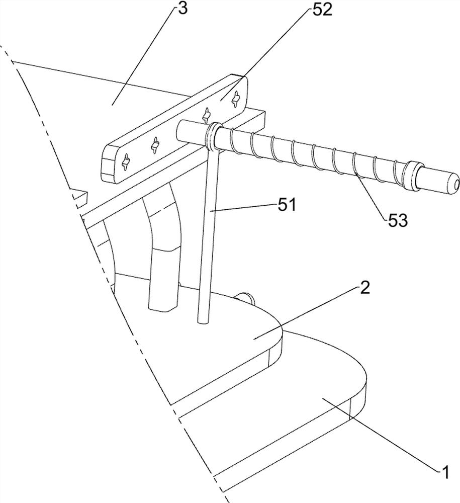
[0058] A fast automatic packaging device for PCB boards, such as Figure 1-3 As shown, it includes a first fixing part 1, a second fixing part 2, a third fixing part 3, a pushing mechanism 4 and a discharging mechanism 5, the first fixing part 1 is provided with a second fixing part 2, and the first fixing part 2 A third fixing part 3 is arranged between the part 1 and the second fixing part 2 , a pushing mechanism 4 is arranged on the second fixing part 2 , and a discharging mechanism 5 is arranged on the third fixing part 3 .

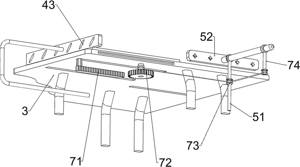
[0059] The pushing mechanism 4 includes a cylinder 41, a first fixed rod 42 and a first push plate 43, the middle rear side of the second fixed part 2 is provided with the first fixed rod 42, and the middle of the second fixed part 2 is provided with a cylinder 41, The rear portion of the cylinder 41 is provided with a first push plate 43 , the first push plate 43 is slidably connected to the first fixing rod 42 , and the first push plate 43 is slidab...

Embodiment 2

[0063] On the basis of Example 1, such as Figure 4-7 As shown, a clamping mechanism 6 is also included. The clamping mechanism 6 includes a splint 61, a second support rod 62, a first rod 63, a second spring 64 and a slide bar 65. Both sides are connected with two second support rods 62, the first rods 63 are connected between the horizontal second support rods 62, two sliding rods 65 are slidably connected between the first rods 63, and the longitudinal The splints 61 are connected between the sliding bars 65 , and the second springs 64 are connected between the horizontal sliding bars 65 .

[0064]When people need to pack the PCB boards, they first move the splint 61 to the outside, so that the slide bar 65 moves to the outside, so that the second spring 64 is stretched, and then the PCB is placed between the splints 61, so that the bottom The PCB board falls onto the third fixing part 3, and then let go. Under the action of the second spring 64, the clamping plate 61 is c...


PUM


Abstract

The invention relates to a packaging device, in particular to a rapid and automatic packaging device for PCBs. The invention provides the rapid and automatic packaging device for the PCBs, which can realize automatic packaging and feeding and discharging. According to the technical scheme, the rapid and automatic packaging device for the PCBs comprises a first fixing part, a second fixing part, a third fixing part, a pushing mechanism and a discharging mechanism, wherein the second fixing part is arranged on the first fixing part; the third fixing part is arranged between the first fixing part and the second fixing part; the pushing mechanism is arranged on the second fixing part; and the discharging mechanism is arranged on the third fixing part. Through cooperation of the pushing mechanism, the discharging mechanism and a clamping mechanism, the PCBs can be automatically packaged, and interval discharging is achieved.

Description

technical field [0001] The invention relates to a packaging device, in particular to a fast and automatic packaging device for PCB boards. Background technique [0002] After the PCB board product processing is completed, in order to facilitate transportation and storage, the PCB board product needs to be packaged. In order to minimize the introduction of dust, grease and other pollution during the packaging process, mechanical equipment is usually used for packaging. [0003] However, the existing packaging device requires manual loading and unloading, and the labor load of workers is large, time-consuming and laborious. Therefore, a fast automatic packaging device for PCB boards that can realize automatic packaging and loading and unloading is now developed. Contents of the invention [0004] In order to overcome the shortcomings of the existing packaging device, the labor load of workers is large, time-consuming and labor-intensive, the technical problem to be solved is...

Claims


Application Information

Patent Timeline
Patent Type & Authority Applications(China)
IPC IPC(8): B65B35/02B65B35/20B65B5/00B65B61/28
CPCB65B35/02B65B35/20B65B5/00B65B61/28
Inventor 钟衍滔
Owner 钟衍滔
Why Eureka
Try Eureka