
Automatic power adjusting system of power adapter

A power adapter and automatic adjustment technology, which is applied in the direction of control/regulation system, electric variable adjustment, output power conversion device, etc., can solve the problems of voltage consumption, voltage reduction, and performance reduction of energy storage power supply of equipment to be charged, etc.

Inactive Publication Date: 2021-06-29
深圳万知达科技有限公司
View PDF0 Cites 0 Cited by
  • Summary
  • Abstract
  • Description
  • Claims
  • Application Information

AI Technical Summary

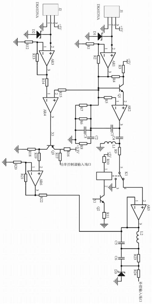
Problems solved by technology

[0002] The power adapter is a power supply conversion device for small portable electronic devices and electronic appliances. The output power of the power adapter is determined by the output voltage and output current, but in fact, once the voltage is determined during the adjustment process of the power adapter, the output The current will also be determined accordingly and controlled by the main circuit board in the power adapter. However, during the power adjustment process of the power adapter, since the bus voltage is a standard voltage, and the bus voltage is charged for the device to be charged after the power is converted by the power adapter, the power adapter It will consume part of the voltage itself, especially the power adapter that has been used for a long time, which will cause the voltage to drop when the power adapter passes through the auxiliary line to the device to be charged. Reduced, long-term low-voltage charging causes the virtual power state of the energy storage power supply of the equipment to be charged

Method used


Image

  • Automatic power adjusting system of power adapter

Examples


Embodiment Construction

[0011] Regarding the aforementioned and other technical contents, features and effects of the present invention, refer to the appended figure 1 It will be apparent from the detailed description of the embodiments. The structural contents mentioned in the following embodiments are all based on the accompanying drawings of the description.

[0012] An automatic power adjustment system for a power adapter, including a bus voltage acquisition module, a secondary line voltage acquisition module, a comparison trigger module, an oscillation control module, and an operational amplifier filter module. The bus voltage acquisition module acquires the voltage value input by the power adapter, and the auxiliary line voltage acquisition module The module collects the voltage value output by the power adapter, and the comparison trigger module compares the output signals of the bus voltage acquisition module and the auxiliary line voltage acquisition module, and converts it into the trigger ...


PUM


Abstract

The invention discloses an automatic power adjusting system of a power adapter. The automatic power adjusting system comprises a bus voltage acquisition module, a secondary line voltage acquisition module, a comparison trigger module, an oscillation control module and an operational amplifier filtering module, wherein the bus voltage acquisition module acquires a voltage value input by the power adapter, the secondary line voltage acquisition module acquires a voltage value output by the power adapter, the comparison trigger module compares output signals of the bus voltage acquisition module and the secondary line voltage acquisition module, when a difference value of output voltages of the bus voltage acquisition module and the secondary line voltage acquisition module is too large, an emitter voltage of a triode Q3 is at a low level relative to a static voltage, the emitter voltage is divided by a resistor R17 and then is directly input into a power controller at the low level, the power controller directly pulls up an output voltage of the power adapter, and meanwhile, a collector electrode of the triode Q3 is directly input into an operational amplifier filtering module after in-phase amplification by an operational amplifier AR6 and is directly input into a power compensation port of the power adapter. The micro-compensation effect on the output voltage of the power adapter is achieved.

Description

technical field [0001] The invention relates to the technical field of power adapters, in particular to an automatic power adjustment system for power adapters. Background technique [0002] The power adapter is a power supply conversion device for small portable electronic devices and electronic appliances. The output power of the power adapter is determined by the output voltage and output current, but in fact, once the voltage is determined during the adjustment process of the power adapter, the output The current will also be determined accordingly and controlled by the main circuit board in the power adapter. However, during the power adjustment process of the power adapter, since the bus voltage is a standard voltage, and the bus voltage is charged for the device to be charged after the power is converted by the power adapter, the power adapter It will consume part of the voltage itself, especially the power adapter that has been used for a long time, which will cause ...

Claims


Application Information

Patent Timeline
Patent Type & Authority Applications(China)
IPC IPC(8): H02M3/156H02M1/32H02M1/14
CPCH02M1/143H02M1/32H02M3/156
Inventor 李宇华
Owner 深圳万知达科技有限公司
Learn More