
Camera three-dimensional holder with semi-arc-shaped sliding rail and working method thereof

A semi-circular arc-shaped, three-dimensional pan-tilt technology, which is applied in the direction of machine platforms/supports, supporting machines, mechanical equipment, etc., can solve the problems of weak load-bearing capacity, dust entering, nodding, etc. The effect of lateral angle adjustment and simple structure

Active Publication Date: 2021-07-02
FUZHOU UNIV
View PDF7 Cites 0 Cited by
  • Summary
  • Abstract
  • Description
  • Claims
  • Application Information

AI Technical Summary

Problems solved by technology

[0003] The active body of the ball head is a sphere, and the sphere can rotate at multiple angles in its outer casing to realize the adjustment of various angles of the camera. Its disadvantage is that its load-bearing capacity is relatively weak, and it is prone to "nodding" after fastening. phenomenon, and because it only relies on a sphere to achieve the adjustment of three dimensions, it often affects the other two dimensions when adjusting one of the dimensions, so it does not have a good effect in fine-tuning the composition; and the ball head is active The ball part of the ball is easy to wear or enter dust, which has a great impact on its adjustment accuracy and service life
[0004] The turbo gimbal determines the direction of the camera through three locks in different directions. It has good load-bearing performance and can adjust the angles of the three dimensions more accurately; the disadvantage is that the operation is relatively slow, and its bearing point and rotation The center coincides, and it is also prone to "nodding" phenomenon
[0005] The hydraulic pan / tilt has high precision, relatively strong load-bearing capacity, and is easy to adjust in each dimension. It is a type of product used by high-end users; It is not easy to repair after the system is damaged, and the performance of hydraulic oil will also be affected in high temperature or low temperature environment

Method used


Image

  • Camera three-dimensional holder with semi-arc-shaped sliding rail and working method thereof
  • Camera three-dimensional holder with semi-arc-shaped sliding rail and working method thereof
  • Camera three-dimensional holder with semi-arc-shaped sliding rail and working method thereof

Examples


Embodiment Construction

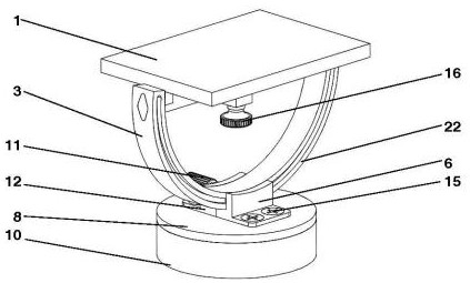
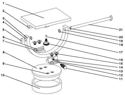
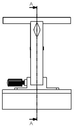
[0022] The camera three-dimensional pan / tilt with semi-arc slide rails of the present invention includes a lower platform 8 and two opposite support blocks (the first support block 6 and the second support block 12) fixed on the upper surface of the lower platform 8, the two A semicircle-arc slide rail 3 is provided for spacing between two oppositely arranged support blocks. The cross-sectional shape of the semicircle-arc slide rail 3 can be a rectangle. For the first screw 11 of the slide rail, the second support block 12 is provided with a first screw hole 14, and the first screw 11 is locked in the first screw hole.

[0023] The opening end of the semicircular slide rail 3 is pierced with a crossbar 21 and an upper platform 1 whose bottom surface is sleeved on the crossbar 21, and the bottom surface of the upper platform 1 is provided with a second screw 16 for fastening the crossbar.

[0024] The structures of the above-mentioned two oppositely arranged support block limit...


PUM


Abstract

The invention relates to a camera three-dimensional holder with a semi-arc-shaped sliding rail and a working method thereof. The three-dimensional holder with the semi-arc-shaped sliding rail is characterized by comprising a lower bedplate and two supporting blocks, wherein the supporting blocks are fixed to the upper surface of the lower bedplate and are oppositely arranged; the semi-arc-shaped sliding rail is arranged between the two oppositely-arranged supporting blocks in a limiting mode; first screws used for fastening the semi-arc-shaped sliding rail are arranged on the supporting blocks in a penetrating mode; a cross rod and an upper bedplate with the bottom surface arranged on the cross rod in a sleeved mode are connected to the open end of the semi-arc-shaped sliding rail in a penetrating mode; and a second screw for fastening the cross rod is arranged on the bottom surface of the upper bedplate.

Description

Technical field: [0001] The invention relates to a camera three-dimensional pan-tilt with a semi-arc slide rail and a working method thereof. Background technique: [0002] At present, the common heads on the market include ball heads, turbo heads and hydraulic heads. [0003] The active body of the ball head is a sphere, and the sphere can rotate at multiple angles in its outer casing to realize the adjustment of various angles of the camera. Its disadvantage is that its load-bearing capacity is relatively weak, and it is prone to "nodding" after fastening. phenomenon, and because it only relies on a sphere to achieve the adjustment of three dimensions, it often affects the other two dimensions when adjusting one of the dimensions, so it does not have a good effect in fine-tuning the composition; and the ball head is active The ball part of the ball is easy to wear or enter dust, which has a great impact on its adjustment accuracy and service life. [0004] The turbo gimb...

Claims


Application Information

Patent Timeline
IPC IPC(8): F16M11/12F16M11/04
CPCF16M11/12F16M11/043
Inventor 于潇雁龚家宝李浩滨郭剑桥陈青桢
Owner FUZHOU UNIV
Learn More