
Opening and drawing device of circuit board stamping die

A technology for stamping dies and circuit boards, which is applied in the direction of motor tools, hand-held tools, manufacturing tools, etc., can solve the problems of difficult molds, looseness, and decreased precision of molds, and achieves a practical, convenient, fast and convenient structure. Effort-saving opening effect

Pending Publication Date: 2021-07-13
佛山市顺德区兆达电子有限公司
View PDF0 Cites 0 Cited by
  • Summary
  • Abstract
  • Description
  • Claims
  • Application Information

AI Technical Summary

Problems solved by technology

The gap between the guide post and the guide sleeve is extremely small, and there is lubricating oil between the guide post and the guide sleeve to form a sucking effect between the guide post and the guide sleeve. It is not easy to open the mold after it is closed, and there is no suitable one at present. The quick and labor-saving tool or device is used to open the mold; the current usual operation method is to use a forklift to fork the upper mold mounting plate to make the upper mold off the ground, and then knock the lower mold to get out of the lower mold. Since the knocking position is At the edge of the lower mold fixing plate, the force of pulling out is not the axial direction of the guide post and guide sleeve, resulting in rigid wear and loosening of the guide post and guide sleeve, so that the gap between the guide post and guide sleeve increases and looseness occurs Phenomenon, the precision of the mold will drop rapidly, and the knocked parts of the mold surface will also be damaged

Method used


Image

  • Opening and drawing device of circuit board stamping die
  • Opening and drawing device of circuit board stamping die
  • Opening and drawing device of circuit board stamping die

Examples


Embodiment Construction

[0020] The present invention will be further described below in conjunction with the accompanying drawings.

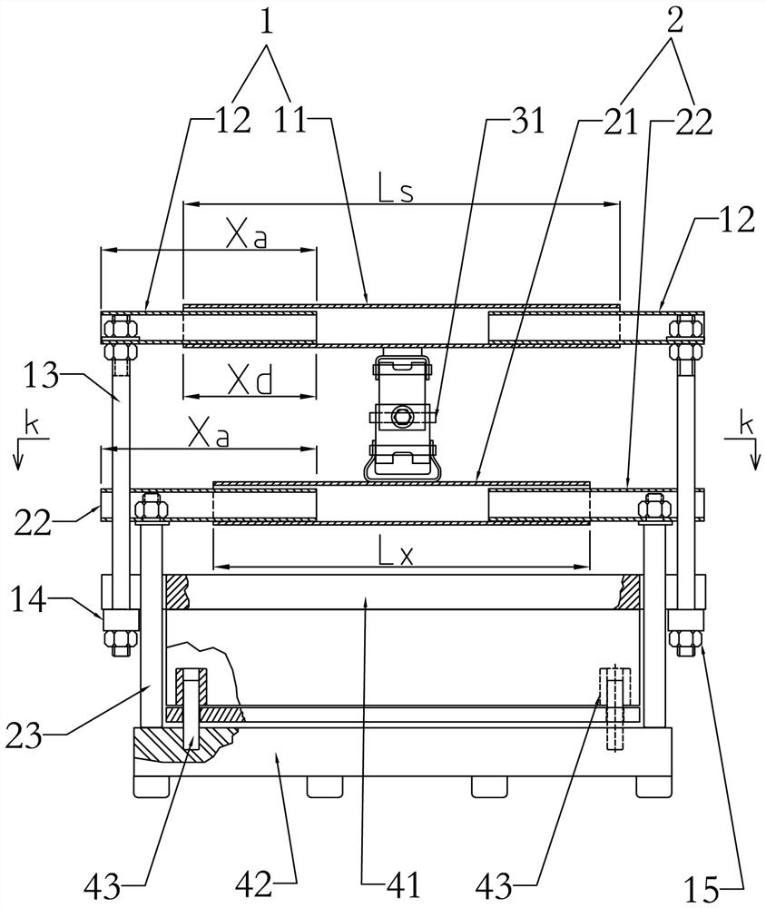
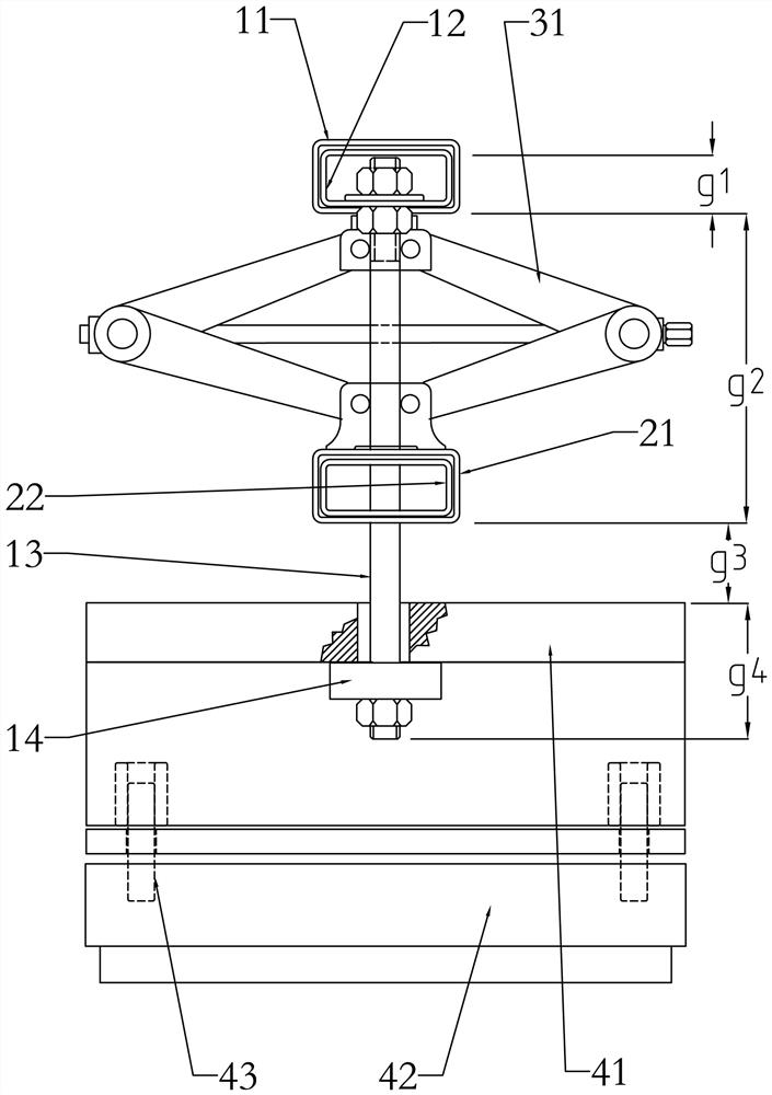
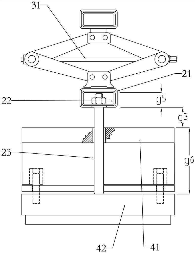
[0021] The drawing device of the circuit board stamping die of the present invention includes an upper cross-arm assembly 1 arranged above the upper die mounting plate 41 for pulling the upper die mounting plate 41; Correspondingly above 41, the lower cross-arm assembly 2 that supports the lower mold fixing plate 42 is provided; the jack 31 that pulls out the mold is placed between the upper cross-arm assembly 1 and the lower cross-arm assembly 2 to pull out the mould. like Figure 1 to Figure 6 Shown, comprise the elevating cross arm 11 that constitutes upper cross arm assembly 1, the upper pulling tube 12 that inserts respectively at lifting cross arm 11 two ends, the outer end 90 ° device pulling rod 13 of two upper pulling tubes 12. The pulling rod 13 is a double-ended screw, the thread length of the upper end is configured to be clamped by double nuts on the uppe...


PUM


Abstract

The invention discloses an opening and drawing device of a circuit board stamping die. The opening and drawing device comprises an upper cross arm assembly arranged above an upper die mounting plate and used for pulling the upper die mounting plate. A lower cross arm assembly for supporting a lower die fixing plate is arranged below the upper cross arm assembly and correspondingly above the upper die mounting plate at the same time. A jack for opening and drawing the die is placed between the upper cross arm assembly and the lower cross arm assembly to implement opening and drawing on the die. According to the opening and drawing device, the portable scissor jack is used as a labor-saving mechanism, heavy dies are easily opened and drawn, and portability and labor saving are realized; and according to more important significance, the die is opened and drawn in a vertical state, a guide pillar and guide sleeve assembly of the die is prevented from being damaged during opening and drawing, and therefore the original precision degree of the die is kept.

Description

technical field [0001] The invention relates to the field of extracting devices, in particular to an extracting device for a stamping die of a circuit board. Background technique [0002] Printed circuit board stamping die is a professional precision mold developed with the development of the electronics industry. With the demand for improving production efficiency in downstream factories and technological progress, printed circuit boards have been changed from single-piece production to jigsaw production. The stamping die of this printed circuit board also becomes larger, making the die relatively heavy. When assembling, correcting and maintaining circuit board stamping dies, it is inseparable to open the upper die and lower die. To maintain the precision of the mold, it depends on the precision guide post and guide sleeve assembly of the mold device and its maintenance. The gap between the guide post and the guide sleeve is extremely small, and there is lubricating oil b...

Claims


Application Information

Patent Timeline
Patent Type & Authority Applications(China)
IPC IPC(8): B25B28/00B25B27/14
CPCB25B28/00B25B27/14
Inventor 蔡炎江
Owner 佛山市顺德区兆达电子有限公司
Learn More