
A pull-top and its pop-top can

A technology for pop-top cans and lids, applied in the field of pop-top can processing, can solve problems such as inability to effectively tear open the opening sheet, inconvenient drinking of the can body beverage, and tearing of the opening sheet 011. The effect of denaturation and ensuring the ability to withstand pressure

Active Publication Date: 2018-07-20
GUANGZHOU RONGXIN CONTAINER
View PDF5 Cites 0 Cited by
  • Summary
  • Abstract
  • Description
  • Claims
  • Application Information

AI Technical Summary

Problems solved by technology

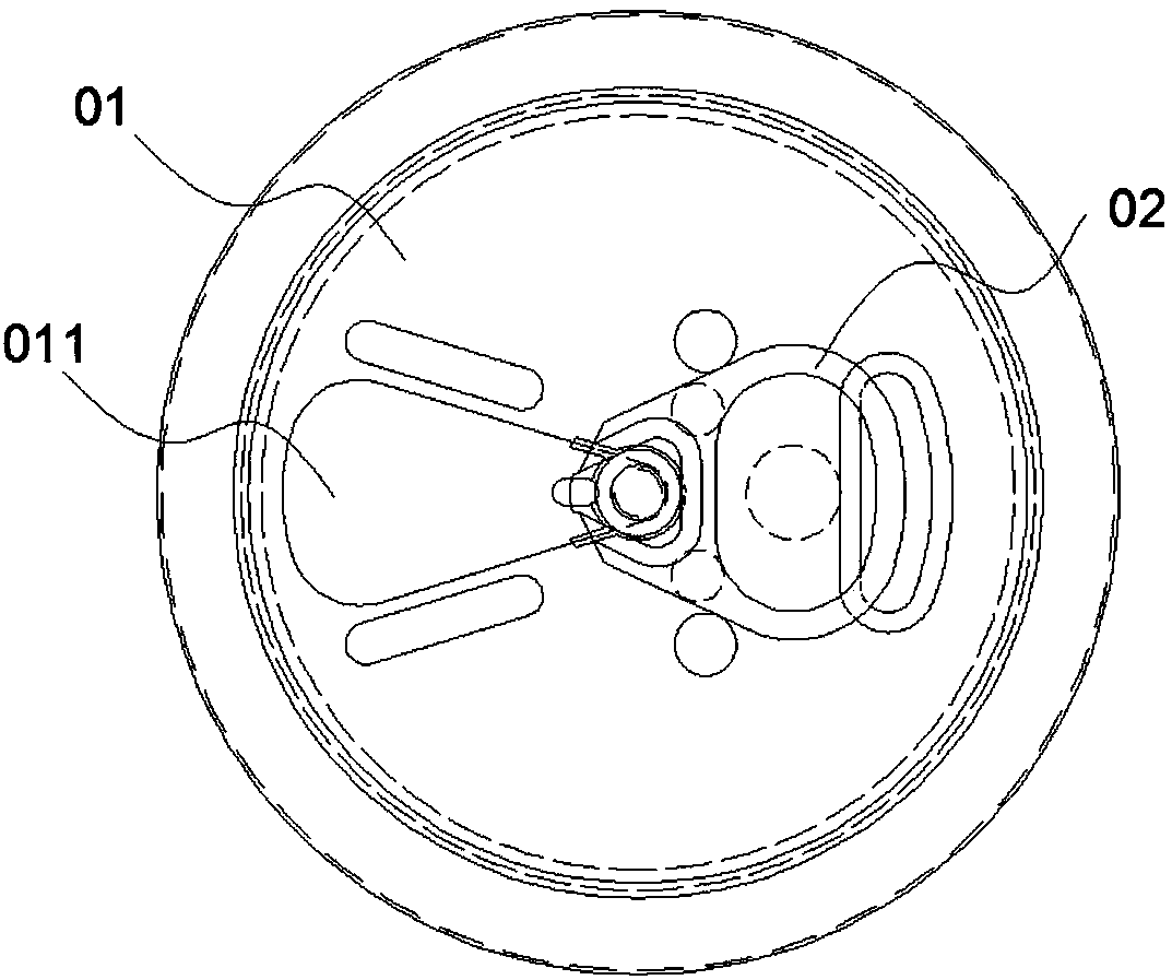
[0004] The thickness of the current opening piece 011 is usually set as a two-stage difference structure that is thinner at the riveted part of the pull ring 02 and thicker at other positions. When the other positions are too thick, when the opening piece 011 is pulled, the pull ring 02 is easily separated from the riveting place and the opening. The opening piece 011 is detached, and the opening piece 011 cannot be effectively torn; or when the opening piece 011 is pulled, the opening piece 011 cannot be pulled apart according to the notch, so that the opening piece 011 is broken, so that the opening piece 11 cannot be effectively torn
And when other positions are too thin, it will affect the pressure bearing capacity of the opening piece 011, which will easily lead to the problem of leakage
In addition, if the surface area of ​​the existing opening piece 011 is set too large, the occurrence of the above-mentioned problems will be exacerbated. Therefore, the existing opening piece 011 is usually set smaller, so that after the opening piece 011 is torn off, the cover surface is exposed. The opening of the can is also small, which also makes it extremely inconvenient for users to drink canned beverages

Method used


Image

  • A pull-top and its pop-top can
  • A pull-top and its pop-top can
  • A pull-top and its pop-top can

Examples


Embodiment Construction

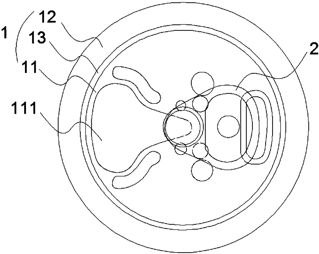
[0025] see figure 2 , which is a schematic diagram of the structure of the embodiment of the pull cover of the present invention. The pull-out cover of this embodiment includes a cover body 1 and a pull ring 2 riveted on the cover body. The cover body 1 includes a cover surface 11 , a cover frame 12 and a collar 13 ; the cover surface 11 and the cover frame 12 are joined by a recessed collar 13 . The top surface of the cover surface 11 is provided with an opening piece 111 extending from the center of the cover surface to the edge of the cover surface, and the pull ring 2 is riveted to the opening piece 111 at the center of the cover surface 11 .

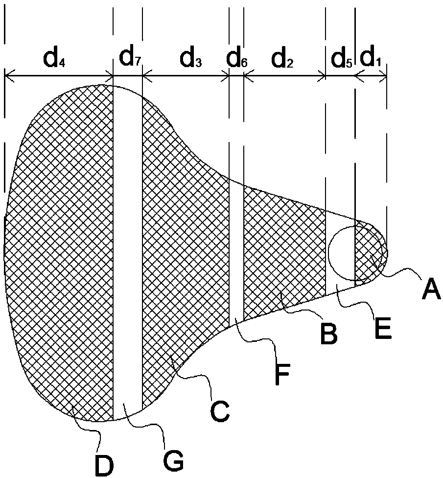
[0026] see image 3 , which is figure 2 Schematic diagram of the structure of the opening sheet shown. The opening piece 111 includes a tear opening part A, a tear part B, a tear part C and a detachment part D distributed sequentially from the center of the cover to the edge of the cover, and there is a thickness difference be...


PUM


Abstract

The invention relates to a ring-pull lid. The ring-pull lid comprises a lid body and a ring-pull. An opening piece formed in a nicking manner is arranged on the top face of the lid body from the center of the lid body to the edge of the lid body. The ring-pull is connected with the opening piece at the center position of the lid body. The ring-pull lid is characterized in that the opening piece comprises a tearing starting part, a tearing and separating part, a tearing part and a disengaging part which are sequentially distributed along the center of the lid body towards the edge of the lid body, and a thickness difference exists between the adjacent parts. Compared with the prior art, the ring-pull lid has the beneficial effects that the opening piece on the ring-pull lid is designed to be provided with the tearing starting part, the tearing and separating part, transitional parts and the disengaging part all of which have thickness differences, the purpose of lifting the opening piece most conveniently and quickly with less labor is achieved, the opening piece can be prevented from being pulled broken, and the problem that the opening piece flies off when the opening piece is torn quickly and other problems can be prevented. The invention further provides a ring-pull can.

Description

technical field [0001] The invention relates to the technical field of pop can processing, in particular to a pop-top lid and a pop-top can. Background technique [0002] As a packaging can for beverages, pop cans are widely used because of their small size, easy portability, and strong freshness retention. [0003] Existing pop cans generally include a tank body and a pull-out lid arranged on the top of the tank body. see figure 1 , which is a structural schematic diagram of an existing pull cover. The pull cover includes a cover body 01 and a pull ring 02. The top surface of the cover body 01 is provided with a ring of opening pieces 011 formed by thumb marks from the center of the cover body to the edge of the cover body. The pull ring 02 is on the cover body. The center is connected with the opening piece 011. When drinking, hook the pull ring 02 with your fingers, and pull the opening piece 011 along the notch, and then tear the opening piece 011 from the cover body...

Claims


Application Information

Patent Timeline
Patent Type & Authority Patents(China)
IPC IPC(8): B65D17/347
CPCB65D17/4011
Inventor 陈卫计永红赖仁华袁远雄
Owner GUANGZHOU RONGXIN CONTAINER
Learn More