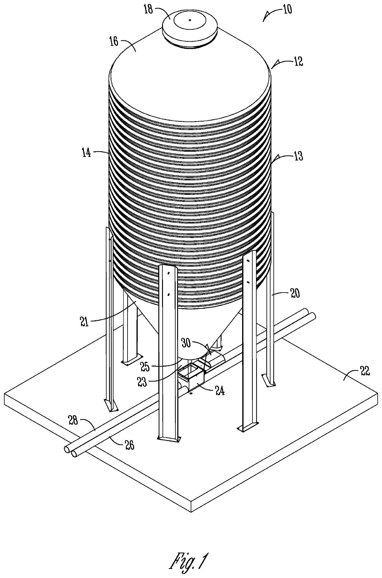
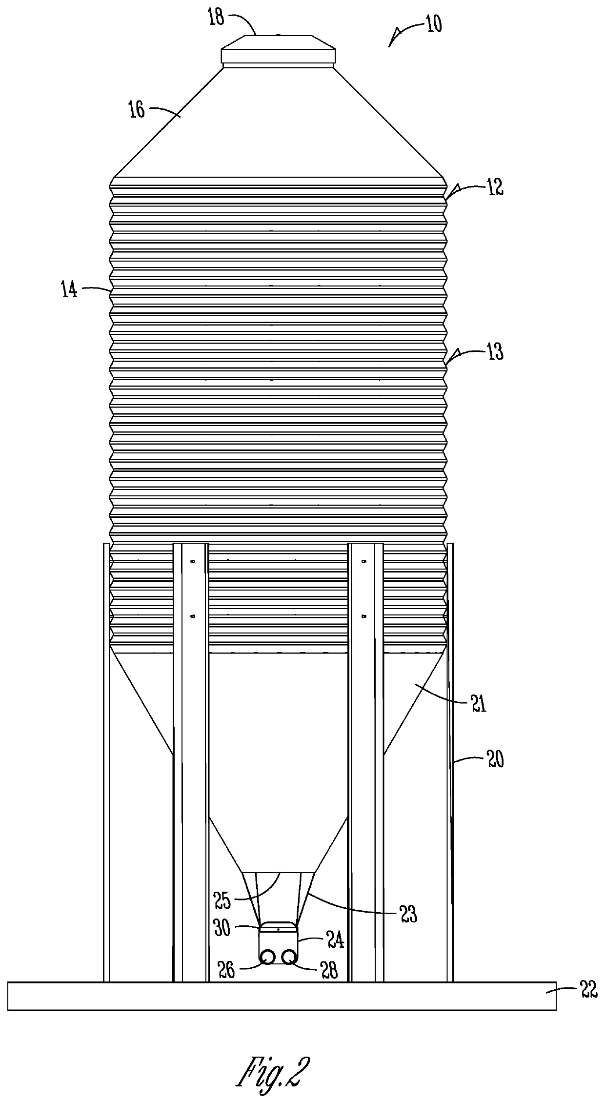
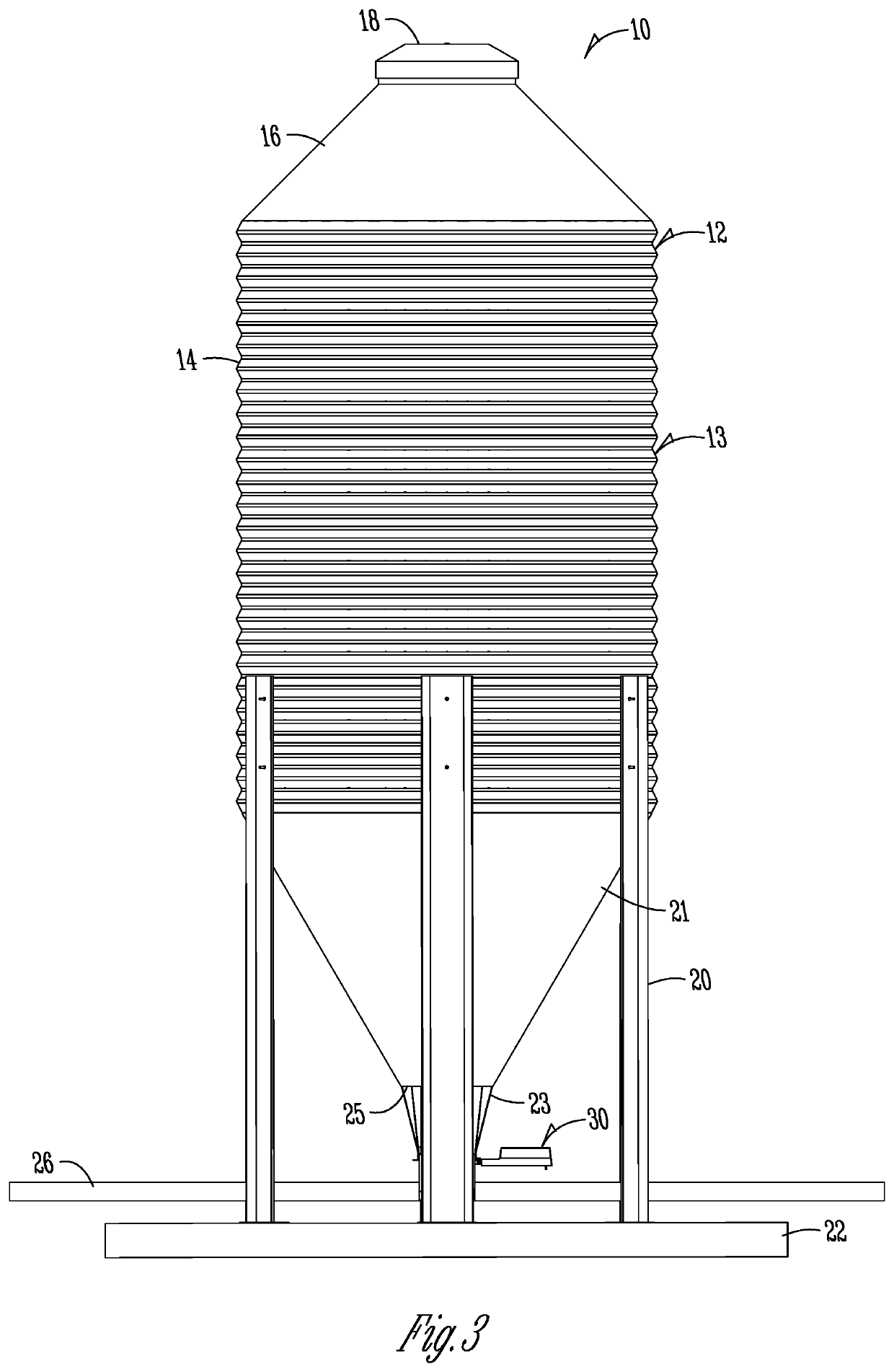
Electric feed bin slide gate

a technology of electric slide gate and feed bin, which is applied in the field of agricultural feed material storage and delivery, can solve the problems of difficult to stop or slow the material to get the door or gate closed, and inconvenient location for a person, etc., to achieve quick and easy installation of the bin slide assembly, quick and easy to open or close, and cost-effective

Pending Publication Date: 2022-03-31
BIN SLIDE LLC
View PDF6 Cites 0 Cited by
  • Summary
  • Abstract
  • Description
  • Claims
  • Application Information

AI Technical Summary

Benefits of technology

[0009]It is a further object, feature, and / or advantage to automate the operation of one or more bin slides of a slide assembly of a feed bin.
[0010]It is still yet a further object, feature, and / or advantage quickly and easily open or close one or more bin slides.
[0011]It is yet another object, feature, and / or advantage to provide a quick and easily installable bin slide assembly.
[0012]It is another object, feature, and / or advantage to provide a near infinitely adjustable bin slide door or gate.
[0013]The systems and / or apparatus disclosed herein can be used in a wide variety of applications. For example, they can be used to control the output of an agricultural feed bin. In addition, they could be used to control generally any opening or output that allows an amount of material from a bulk storage for some end use.
[0014]It is preferred that the bin slide assembly as shown and / or described be safe, cost effective, and durable. The system is generally used in areas of high volumes of particulate material, and should withstand dust, debris, and other particles that could cause breakage of the system.

Problems solved by technology

Such a configuration is labor intensive, difficult, and oftentimes inconvenient.
First, as the bins utilize gravity to move the particulate material, it can be difficult to stop or slow the material to get the door or gate closed.
In addition, due to location of the door or gate on the underside of the outlet, the location can be inconvenient for a person to have to work around to access to both open and close.
Making sure that a person is watching and quick to act to close the gate or door adds another layer to the difficulty, which includes the timely opening of a new bin when a separate bin runs out of material.
Still additional issues exist with current gates.
For example, it takes a lot of time to change a slide.

Method used


Image

  • Electric feed bin slide gate
  • Electric feed bin slide gate
  • Electric feed bin slide gate

Examples


Embodiment Construction

[0060]The present disclosure is not to be limited to that described herein. Mechanical, electrical, chemical, procedural, and / or other changes can be made without departing from the spirit and scope of the invention. No features shown or described are essential to permit basic operation of the invention unless otherwise indicated.

[0061]Unless defined otherwise, all technical and scientific terms used above have the same meaning as commonly understood by one of ordinary skill in the art to which embodiments of the invention pertain.

[0062]The terms “a,”“an,” and “the” include both singular and plural referents.

[0063]The term “or” is synonymous with “and / or” and means any one member or combination of members of a particular list.

[0064]The terms “present invention” or “invention” are not intended to refer to any single embodiment of the particular invention but encompass all possible embodiments as described in the specification and the claims.

[0065]The term “about” as used herein refer...


PUM


Abstract

A bin slide assembly controls the amount of particulate material that is transferred from an agricultural bin, such as a feed bin, to a feed line for delivery for some end use. To allow the control to be automated or otherwise electronically operated, electronic motors can operate one or more slides that selectively block an outlet of the feed bin. The electronic control provides for a more precise operation of the bin slide to control the amount of material. In addition, the use of the electric motor provides a more convenient and easier to operate system. The slides are connected to screws, such as acme screws, which are activated by operation of the electric motor to rotate the screw, which translates the slide between open and closed configurations.

Description

CROSS REFERENCE TO RELATED APPLICATIONS[0001]This application claims priority under 35 U.S.C. § 119 to provisional patent application U.S. Ser. No. 63 / 198,094, filed Sep. 29, 2020. The provisional patent application is herein incorporated by reference in its entirety, including without limitation, the specification, claims, and abstract, as well as any figures, tables, appendices, or drawings thereof.FIELD OF THE INVENTION[0002]The invention relates generally to the storage and delivery of particulate material and, more particularly, to the storage and delivery of agricultural feed material. More particularly, but not exclusively, the invention relates to a system, apparatus, and / or corresponding method of an electric slide gate for use in selectively delivering an amount of particulate material for a bin, such as a bin containing agricultural feed material.BACKGROUND OF THE INVENTION[0003]Agricultural bins are used for a variety of uses. One such use includes the storage of a parti...

Claims


Application Information

Patent Timeline
Patent Type & Authority Applications(United States)
IPC IPC(8): A01F25/20A01F25/16
CPCA01F25/2018A01F25/163B65G3/04B65G53/36B65G53/12B65G65/40
Inventor SORENSON, JOSHUA
Owner BIN SLIDE LLC
Why Eureka
Try Eureka