Structure and method for realizing dual-redundancy Flash

A technology of dual redundancy and control method, the redundancy applied in the hardware is used for data error detection, response error generation, instruments and other directions, which can solve problems such as firmware update failure, CPU failure, and CPU failure to load BIOS normally. , to achieve the effect of easy maintenance and strong availability

Pending Publication Date: 2021-07-13
SHANDONG YINGXIN COMP TECH CO LTD
View PDF3 Cites 3 Cited by
  • Summary
  • Abstract
  • Description
  • Claims
  • Application Information

AI Technical Summary

Problems solved by technology

[0003] In the prior art, the existing method for realizing switching is to control the CPU reset and the selection of the main Flash and the standby Flash by the CPLD. After loading BIOS from the main Flash fails, the CPLD selects the standby Flash and outputs a reset signal to the CPU. Realize that the CPU loads the BIOS from the standby Flash to start, and when the CPU is working, the firmware update to the Flash is completed. However, in the prior art, when both Flashes cannot load the BIOS, the firmware update fails, and when there is a lack of necessary update content , may lead to the problem that the CPU cannot load the BIOS normally, and the CPU cannot work

Method used


Image

  • Structure and method for realizing dual-redundancy Flash
  • Structure and method for realizing dual-redundancy Flash
  • Structure and method for realizing dual-redundancy Flash

Examples


Embodiment Construction

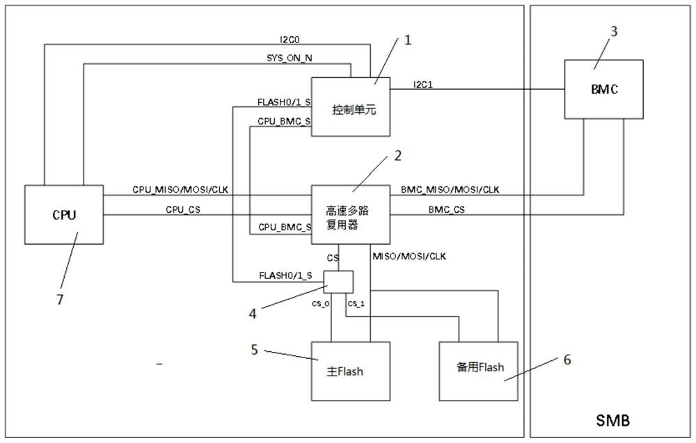
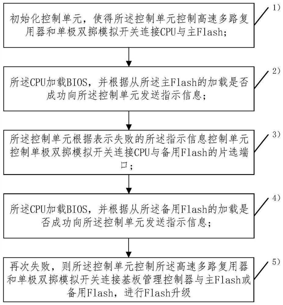
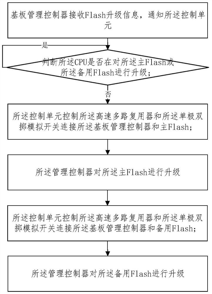
[0040] In order to make the objects, technical solutions, and advantages of the present application, the technical solutions in the present application embodiment will be clearly described, and the described embodiments will be described in conjunction with the drawings in the present application embodiment. It is part of the embodiments of the present application, not all of the embodiments. Based on the embodiments in the present application, all other embodiments obtained by those of ordinary skill in the art without making creative labor are the scope of the present application. among them, figure 1 A schematic of a structure of a double redundant flash is provided for the embodiment of the present application; figure 2 A flow chart of a method of achieving dual redundancy Flash is provided herein; image 3 A flowchart of the substrate management controller provided in the present application embodiment for Flash upgrade; Figure 4 A flowchart of the Flash upgrade for the CPU pr...


PUM


Abstract

On one hand, the invention relates to a Flash structure for realizing dual redundancy, and the structure comprises a control unit, and the control unit is electrically connected with a selection module; the control unit controls the selection module to be connected with the substrate management controller and the main Flash or the standby Flash, or controls the selection module to be connected with the CPU and the main Flash or the standby Flash; and the control unit is electrically connected with the substrate management controller and the CPU. On the other hand, the invention relates to a method for realizing the dual-redundancy Flash. The method comprises the following steps of: automatically switching the main Flash and the standby Flash to be connected with the CPU in a BIOS loading process; when the BIOS cannot be loaded, the main Flash and the standby Flash are automatically switched to be connected with the substrate management controller in the Flash upgrading process through the substrate management controller. According to the method and the device, Flash upgrading can be carried out on the CPU or the baseboard management controller, when the two Flash cannot load the BIOS, the CPU cannot work, and remote upgrading can be carried out through the baseboard management controller, so that the BIOS is easier to maintain and higher in reliability.

Description

Technical field [0001] The present application relates to the field of Flash design, and more particularly to the structure and method of realizing dual redundant Flash. Background technique [0002] The CPU is the core component of the computer device. When the CPU is started, it is necessary to load the BIOS from the flash; in the prior art, in order to ensure that the ability to load the BIOS is successful, Flash is redundantly designed, set a primary flash and one Alternate Flash; When it is not possible to load from the primary flash to the BIOS, automatically switch to another. [0003] In the prior art, the existing method of switching is to control the CPU reset and the selection of CPU reset and the main flash and alternate flash. When the BIOS is loaded from the primary flash, the alternate flash is selected by the CPLD, and the reset signal is output to the CPU. Implementing the CPU to load the BIOS from the alternate flash, and when the CPU is working, complete the fi...

Claims


Application Information

Patent Timeline
Patent Type & Authority Applications(China)
IPC IPC(8): G06F8/654G06F11/18
CPCG06F8/654G06F11/187
Inventor 郭建璞韩威薛广营
Owner SHANDONG YINGXIN COMP TECH CO LTD
Why Eureka
Try Eureka