
Laid cloth roll clamping mechanism for wind power blade mold and application of laid cloth roll clamping mechanism

A technology of wind power blade and clamping mechanism, which is applied in the field of wind power blade mold laying roll clamping mechanism, which can solve the problems of gradual change and non-fitting of profiles, etc., and achieve the effects of liberating productivity, good fit, and convenient operation

Pending Publication Date: 2021-07-20
GURIT TOOLING (TAICANG) CO LTD
View PDF0 Cites 0 Cited by
  • Summary
  • Abstract
  • Description
  • Claims
  • Application Information

AI Technical Summary

Problems solved by technology

[0004] Purpose of the invention: The purpose of the present invention is to solve the deficiencies of the prior art, to provide a wind power blade mould-spreading roll clamping mechanism and its application. It solves the problem of the gradual change of the profile in the direction of the blade axis. The application of this device solves the existing problems of rapid switching of the spreading roll and the non-fitting of the profile. In the actual production process, it is effectively combined with labor to share labor. Repetitive labor in the spreading process greatly liberates productivity and improves work efficiency

Method used


Image

  • Laid cloth roll clamping mechanism for wind power blade mold and application of laid cloth roll clamping mechanism
  • Laid cloth roll clamping mechanism for wind power blade mold and application of laid cloth roll clamping mechanism
  • Laid cloth roll clamping mechanism for wind power blade mold and application of laid cloth roll clamping mechanism

Examples


Embodiment

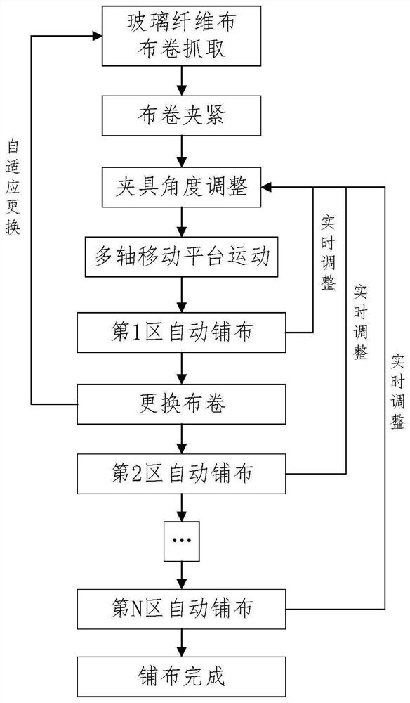
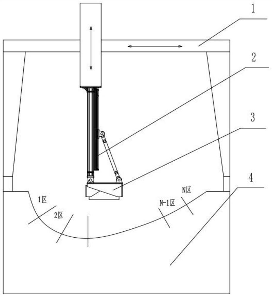
[0056] Step 1: Place the multi-axis mobile platform 1 on the mold 100, and manually transport the glass fiber cloth roll of one blade to the designated place around the mold 100. After the central control terminal turns on the switch for changing the cloth roll, the glass fiber cloth roll After the cylinder 305 in the fixture 3 receives the power-on work button sent by the PLC circuit, the piston rod on the cylinder 305 connected to the L-shaped clamping plate 308 pushes the L-shaped clamping plate 308 to stretch out from the support frame 306. At this time, The support bearing A309 moves under the drive of the L-shaped clamping plate 308 until the position sensor on the support frame 306 sends the limit position of the L-shaped clamping plate 308 to the PLC circuit, and the PLC circuit sends a power-off stop signal to the cylinder 305 Signal, fix one end of the glass fiber cloth roll on the support bearing B307 by manual or mechanical arm, and the other end of the glass fiber ...


PUM


Abstract

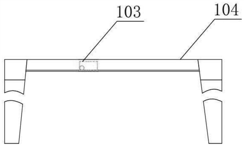
The invention discloses a laid cloth roll clamping mechanism for a wind power blade mold and application of the laid cloth roll clamping mechanism. The laid cloth roll clamping mechanism comprises a multi-axis moving platform, a laid cloth clamp supporting and adjusting mechanism and a glass fiber cloth roll clamp. One end of the laid cloth clamp supporting and adjusting mechanism is connected with the glass fiber cloth roll clamp, and the other end of the laid cloth clamp supporting and adjusting mechanism and the multi-axis moving platform are fastened. According to the mechanism, switching is carried out according to the models of different blades, laid cloth is attached to the curved surface of the blade mold, the problems of gradual changing of molded surfaces in the axis direction of the blades and the like are solved, an application method of the mechanism solves the problems that at present, laid cloth rolls are rapidly switched and molded surfaces are not attached, in the actual production process, the mechanism is effectively combined with manual work, repeated work in the manual cloth laying process is shared, productivity is liberated to a great degree, and the working efficiency is improved.

Description

technical field [0001] The invention relates to the field of wind power blade moulds, in particular to a wind power blade mould-laying roll clamping mechanism and its application. Background technique [0002] With the country's vigorous development of clean energy, the wind power industry has also developed rapidly. The development and utilization of wind power has gradually replaced thermal power generation and has become one of the largest commercial industries in the field of new energy. As a clean and renewable energy, wind energy has been paid more and more attention by countries all over the world. Its reserves are huge. The global wind energy is about 2.74×10⁹MW, of which the usable wind energy is 2×10⁷MW, which is 10 times larger than the total amount of water energy that can be developed and utilized on the earth. Wind has been used by people for a long time, mainly through windmills to pump water, grind flour, etc., but now, people are interested in how to use wi...

Claims


Application Information

Patent Timeline
Patent Type & Authority Applications(China)
IPC IPC(8): B29C70/38B29C70/54
CPCB29C70/38B29C70/54
Inventor 乔治陆家麟孟令辉
Owner GURIT TOOLING (TAICANG) CO LTD
Learn More