A hemostatic forceps with adjustable clamping angle

A pliers and angle technology, applied in the field of pliers, can solve problems such as easy to puncture nearby tissues, easy fatigue of nurses and doctors, etc.

Active Publication Date: 2022-04-12
SUZHOU FRANKENMAN MEDICAL EQUIP
View PDF4 Cites 0 Cited by
  • Summary
  • Abstract
  • Description
  • Claims
  • Application Information

AI Technical Summary

Problems solved by technology

[0003] Hemostats have a wide range of functions and are often used in the operating room, and are usually held by nurses to help doctors perform operations. Hemostats often need to be used carefully because of their sharp tips during use, but when the operation is in progress According to the degree of difficulty, the time to perform is also different. Some operations need to be performed for a long time. At this time, nurses and doctors will be easily tired. When the nurse performs the operation of the hemostat, it is necessary to accurately control the opening and closing angle of the hemostat. Avoid poking the tissue near the blood vessel when the opening and closing angle is too large, it is easy to puncture the nearby tissue

Method used


Image

  • A hemostatic forceps with adjustable clamping angle
  • A hemostatic forceps with adjustable clamping angle
  • A hemostatic forceps with adjustable clamping angle

Examples


Embodiment 1

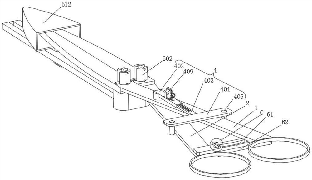
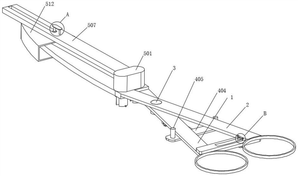
[0030] Example 1, such as Figure 1-9 As shown, the present invention provides a hemostatic forceps, specifically the hemostatic forceps with the function of adjusting the clamping angle, and further includes a protective function. The specific structure is that it includes a first long rod 1 and a position-limiting structure 4, the inner wall of the first long rod 1 is rotatably connected with a rotating shaft 3, the surface of the rotating shaft 3 is rotatably covered with a second long rod 2, the first long rod 1 and the second The surface of the long rod 2 is fixedly connected with a finger ring, and the surface of the rotating shaft 3 is provided with a limiting structure 4 .

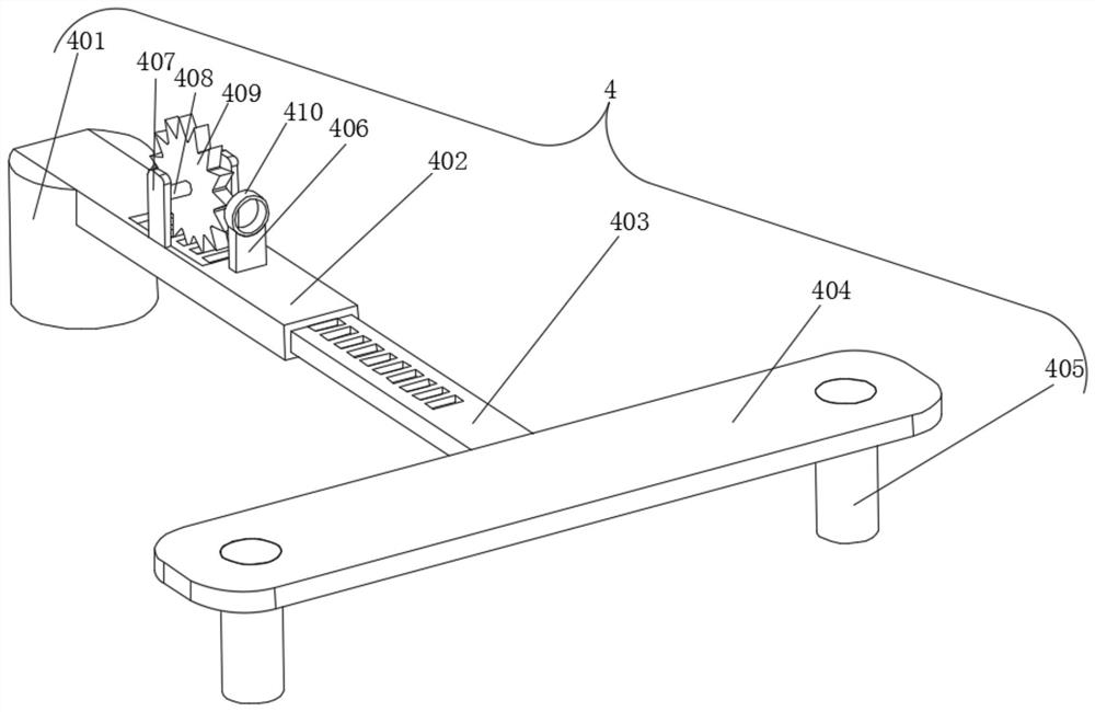
[0031] Let's talk about the specific setting and effect of its position-limiting structure 4, protective structure 5 and auxiliary structure 6 in detail below.

[0032] Such as figure 1 and image 3 As shown, the limiting structure 4 includes a cylinder 401, the surface of the cylinder 401 is fi...

Embodiment 2

[0036] Embodiment 2, on the basis of embodiment 1, as figure 1 and Figure 7 As shown, the surface of the first long pole 1 is provided with an auxiliary structure 6, the auxiliary structure 6 includes a first connection frame 61, the surface of the first connection frame 61 is fixedly connected with the first long pole 1, and the second long pole 2 is relatively The position of a connection frame 61 is fixedly connected with a second connection frame 62, the surfaces of the first connection frame 61 and the second connection frame 62 are both provided with through holes, and the position of the first connection frame 61 relative to the through holes is fixedly connected with a cylinder 63, the inside of the cylinder 63 is slidingly inserted with a long column 64, the surface of the long column 64 is fixedly connected with a rectangular bar 65, and the end of the rectangular bar 65 close to the cylinder 63 is fixedly connected with two fixed columns 66, and the long column 64 ...


PUM


Abstract

The invention provides a hemostatic forceps with adjustable clamping angle, the surface of the rotating shaft is provided with a limiting structure, the limiting structure includes a cylinder, the surface of the cylinder is fixedly connected with the rotating shaft, and the surface of the cylinder is fixedly connected with A frame body, a slide bar is slidably inserted inside the frame body, and a long plate is fixedly connected to the end of the slide bar away from the cylinder, and the surface of the long plate is fixedly connected to a limit column, and the number of the limit column is Two, the two position-limiting columns are respectively located at two ends of the first long rod and the second long rod far away from each other. The invention solves the problem that nurses need to accurately control the opening and closing angle of the hemostat when performing the operation of the hemostat, and some operations need to be performed for a long time. The tissue near the blood vessel is easy to puncture the nearby tissue.

Description

technical field [0001] The invention relates to the technical field of pliers, in particular to a hemostatic pliers with adjustable clamping angle. Background technique [0002] A hemostat is a surgical instrument that clamps blood vessels to block blood. Rescue the patient in the case of bleeding, after taking the hemostatic drug, use the hemostatic forceps to clamp the large artery of the blood vessel to prevent the blood from flowing out. The principle of use of the hemostat is to clamp blood vessels or fur like clips, but they are sterilized. Hemostatic forceps are divided into large, small, toothed, toothless, straight, and curved. Different types of hemostatic forceps are selected according to different operating parts. The teeth next to the hemostat handle help keep the hemostat in place while holding an object, preventing it from falling out. [0003] Hemostats have a wide range of functions and are often used in the operating room, and are usually held by nurses ...

Claims


Application Information

Patent Timeline
Patent Type & Authority Patents(China)
IPC IPC(8): A61B17/12A61B17/28
CPCA61B17/12A61B17/2833A61B2017/12004A61B2017/2808
Inventor 尤晓锦曹锐
Owner SUZHOU FRANKENMAN MEDICAL EQUIP
Why Eureka
Try Eureka