
Clamping device for drilling jig for rocker arm support of diesel engine

A technology of rocker arm support and clamping device, which is applied in the direction of drilling molds for workpieces, etc., can solve the problems of reduced machining accuracy of parts, increased cost of fixtures, and increased times of clamping by operators, so as to ensure positioning accuracy and solve problems. The effect of compressing the flat position

Active Publication Date: 2022-06-24
JIANGSU UNIV OF SCI & TECH
View PDF0 Cites 0 Cited by
  • Summary
  • Abstract
  • Description
  • Claims
  • Application Information

AI Technical Summary

Problems solved by technology

As a result, the cost of fixtures increases, the number of times the operator clamps increases, the labor intensity increases, and the more times the parts are installed, the precision of the parts is also reduced.

Method used


Image

  • Clamping device for drilling jig for rocker arm support of diesel engine
  • Clamping device for drilling jig for rocker arm support of diesel engine
  • Clamping device for drilling jig for rocker arm support of diesel engine

Examples


Embodiment Construction

[0031] In order to make the purpose and technical scheme of the present invention clearer, the present invention will be further described below in conjunction with the accompanying drawings and embodiments:

[0032] It will be understood by those skilled in the art that, unless otherwise defined, all terms (including technical and scientific terms) used herein have the same meaning as commonly understood by one of ordinary skill in the art to which this invention belongs.

[0033] The meaning of "left, right, up, down, front and back" described in the present invention means that when the reader is facing the drawings, the left side of the reader is left, the right side of the reader is right, and the reader is right. The upper side is the upper side, the lower side of the reader is the lower side, the front side of the paper in front of the reader is the front, and the side facing the reader is the back side, which is not a specific limitation of the present invention. The f...


PUM


Abstract

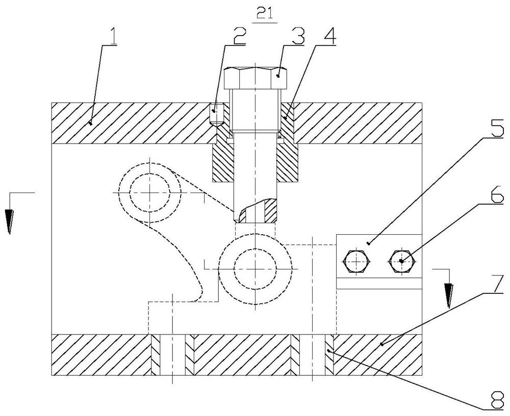
The utility model relates to a clamping device for a drilling fixture of a rocker arm support of a diesel engine. Including the clamp body, the first combination drill bushing, the second combination drill bushing, the support sleeve, and the limit block; the clamp body is composed of four templates up, down, front and back into a square shape; for holes with low precision, use the first combination drill bushing , including the drill sleeve positioning nut, drill sleeve screw, and anti-rotation pin; the drill sleeve positioning nut is responsible for positioning and fixing the thread for the drill sleeve screw. The drill sleeve screw is not only the drill sleeve, but also the compression screw of the part in the fixture. For precision For higher holes, use the second combined drill sleeve, including fixed drill sleeve, movable drill sleeve, coil seat, and compression nut; the fixed drill sleeve and movable drill sleeve form a drill sleeve set, which is responsible for drilling, expanding and reaming of parts , the coil seat and the compression nut bear the compression effect of the parts in the fixture. The fixture uses the combination of the drill sleeve and the compression device to realize the drilling on the smaller part plane, which not only ensures the drilling of the parts, but also can use the Plane to compress the parts.

Description

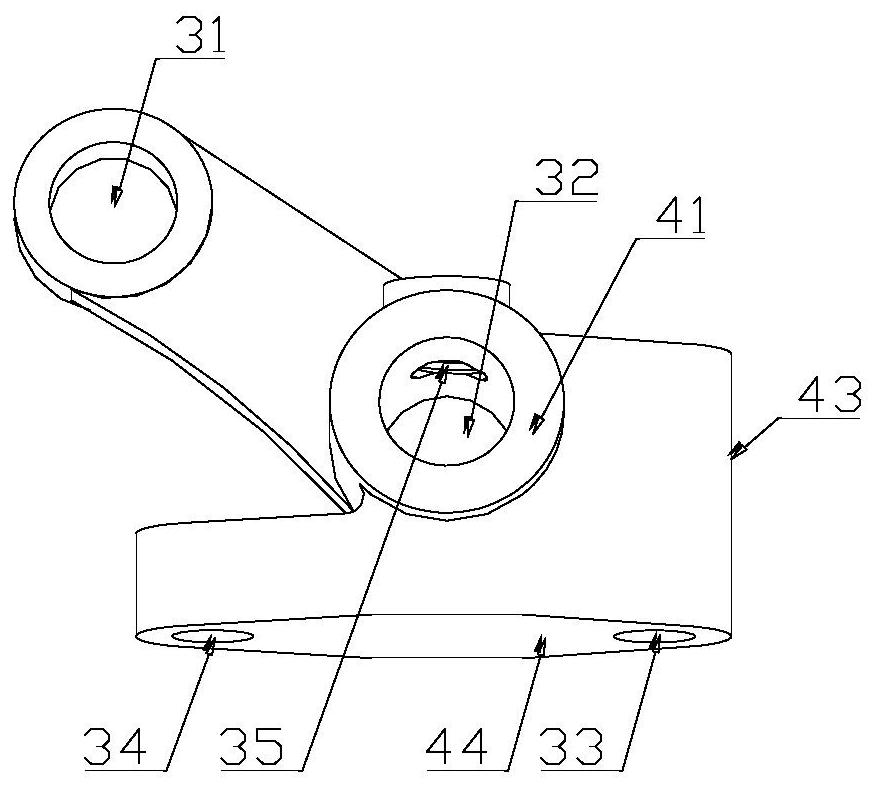
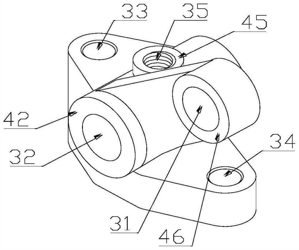
technical field [0001] The invention relates to a clamping device for a clamp, in particular to a clamping device for a drill clamp for a rocker arm support of a diesel engine, and belongs to the technical field of mechanical manufacturing technology of diesel engine parts. Background technique [0002] Diesel engine rocker arm supports are generally castings, such as figure 1 , figure 2 As shown in the figure, compared with the general machining parts, the size of this part is small and the shape is complex; the upper and lower, front and rear directions of the part are provided with porous holes, and there are multiple facets with different heights in the same direction, and each facet is provided with There is a hole. Therefore, in order to improve the machining accuracy of the part and improve the machining efficiency, after the part is milled, a drill jig is used to machine the holes on the part. [0003] Due to the small size of the parts, there are many holes to be...

Claims


Application Information

Patent Timeline
Patent Type & Authority Patents(China)
IPC IPC(8): B23B47/28
CPCB23B47/28B23B2247/12
Inventor 王兆晖凌有临冯拥军刘翠彭帆郭霞飞窦子轩
Owner JIANGSU UNIV OF SCI & TECH
Learn More