Hole site marking tool and method for marking hole site on assembly part

An assembly and marking technology, which is applied to the tools on the back and the assembly field of two parts on the aircraft, can solve the problem that the hole projection on the side of the assembly cannot be found, the edge distance d of the F row of holes cannot be guaranteed, and skinning cannot be realized Issues such as BF row hole marks, to achieve the effect of improving dispatch efficiency

Active Publication Date: 2021-07-23
COMAC +1
View PDF5 Cites 5 Cited by
  • Summary
  • Abstract
  • Description
  • Claims
  • Application Information

AI Technical Summary

Problems solved by technology

[0004] The above method is suitable for the case where the assembly parts are small, and there are reference planes and lines that can transmit hole positioning information between the assembly parts. Reference planes, lines that can project holes on one side of an assembly to the other
[0005] like figure 2 As shown, the skins A and B have been assembled, and now it is necessary to make holes in the riveting area of ​​the A area shown in the figure. The drawing shows the distance D of the fastener holes on the skin A, and the two rows The spacing L of the fasteners can theoretically mark the position of the F row of holes on the side of the skin B according to the edge line of the skin A and the value of D+L, and then obtain the position of the F row of holes on the side of the skin B The edge distance d, but in fact, because the skin A and skin B have been assembled, forming a single-sided closed state, the edge of skin A cannot be known on the side of skin B, so it cannot be realized on the skin B-side. Marking of row of holes on side F
When the holes are made without knowing the distance d of the F row of holes on the side of the skin B, once there is an error between the actual and the theoretical overlap W of the skin, it will result in the edge of the F row of holes on the skin B. distance d cannot be guaranteed

Method used


Image

  • Hole site marking tool and method for marking hole site on assembly part
  • Hole site marking tool and method for marking hole site on assembly part
  • Hole site marking tool and method for marking hole site on assembly part

Examples


Embodiment Construction

[0075] The present invention will be further described below in conjunction with the accompanying drawings and embodiments, so as to more clearly connect the inventive principle and beneficial technical effects of the present invention.

[0076] For the convenience of describing the present invention, the terms used herein are explained as follows:

[0077] Proximity: Approaching or facing a face or end of an assembly;

[0078] Far: The face or end away from or facing away from an assembly;

[0079] Front: In the embodiments listed in the specification, the front is the marking surface of the assembly, and in other embodiments, it can also be called the back:

[0080] Back side: In the enumerated embodiments, the side opposite to the front side can also be referred to as the front side opposite to the back side in other embodiments.

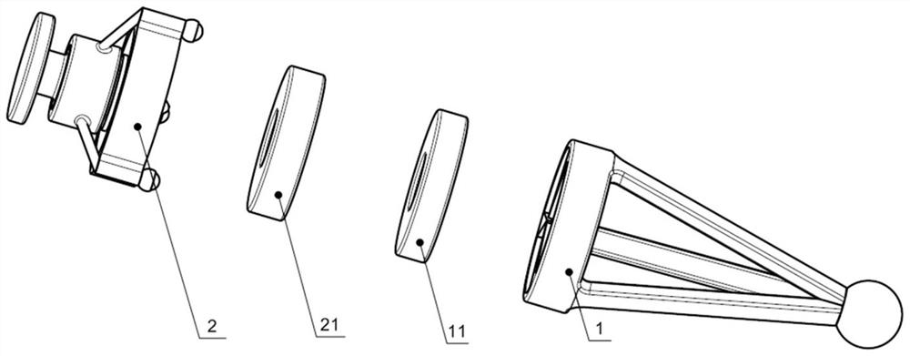
[0081] image 3 and 4 Shown is a tool for marking holes on the back of an assembly 3 according to the present invention, that is, a hole mar...


PUM


Abstract

The invention relates to a hole site marking tool and a method for marking a hole site on an assembly part. The hole site marking tool comprises a hole locator with a locator magnet and a hole marker with a marker magnet and a marking component. The locator magnet comprises a locator near surface facing a pre-marking surface of the assembly part, the locator magnet is in a circular ring shape with a locator center hole, and a reserved mark in the pre-marking surface can be seen through the locator center hole. The marker magnet comprises a marker near surface facing a to-be-marked surface of the assembly part, and the marker magnet is in a circular ring shape with a marker center hole. The marking component comprises a near end facing the to-be-marked surface of the assembly part and a far end opposite to the near end, the marking component is arranged in the marker center hole and moves axially relative to the marker magnet, and therefore the near end of the marking component is in the to-be-marked surface of the assembly part, and a hole site corresponding mark is left at the position corresponding to the reserved mark. The hole site marking tool is used in the method for marking the hole site on the assembly part.

Description

technical field [0001] The present invention relates to a hole position marking tool for marking the hole position of an assembly and a method for marking the hole position on the assembly, in particular to a tool capable of marking the front hole of the assembly to the back of the assembly, An assembly can be a pair of parts or another number of parts. This tool is especially used for the assembly of two parts on an aircraft. Background technique [0002] When there is an assembly relationship between two or more parts on the aircraft, the drawing generally only shows the fastener hole position information on one of the parts. During actual operation on site, mark the positioning holes on the parts with hole position information according to the drawings. Then mark the hole on another part through other reference planes, lines, etc., and then check whether the hole is too close to the edge of the part or whether the hole is in the chamfering area of ​​the part, and then pr...

Claims


Application Information

Patent Timeline
Patent Type & Authority Applications(China)
IPC IPC(8): B25H7/00
CPCB25H7/00
Inventor 苟鹏坡帅国武陈晨
Owner COMAC
Why Eureka
Try Eureka