Steel rail fat edge grinding unit

A technology for steel rails and fat edges, applied in the directions of rails, laying rails, rail maintenance, etc., can solve the problems of inability to adjust the grinding method, single grinding device strategy, etc., to improve the quality of grinding operations, improve the efficiency and quality of grinding operations, and improve operations. The effect of efficiency

Pending Publication Date: 2021-07-23
ZHUZHOU TIMES ELECTRONICS TECH CO LTD
View PDF1 Cites 0 Cited by
  • Summary
  • Abstract
  • Description
  • Claims
  • Application Information

AI Technical Summary

Problems solved by technology

[0006] In view of this, the purpose of the present invention is to provide a rail fat edge grinding unit to solve the problem that the existing grinding device has a single strategy, cannot adjust the grinding method according to actual needs, and cannot simultaneously meet the requirements of a large grinding amount, and remove the plastic fat edge of the rail. , and can ensure that the rail profile and surface roughness after grinding meet the technical problems

Method used


Image

  • Steel rail fat edge grinding unit
  • Steel rail fat edge grinding unit
  • Steel rail fat edge grinding unit

Examples


Embodiment 1

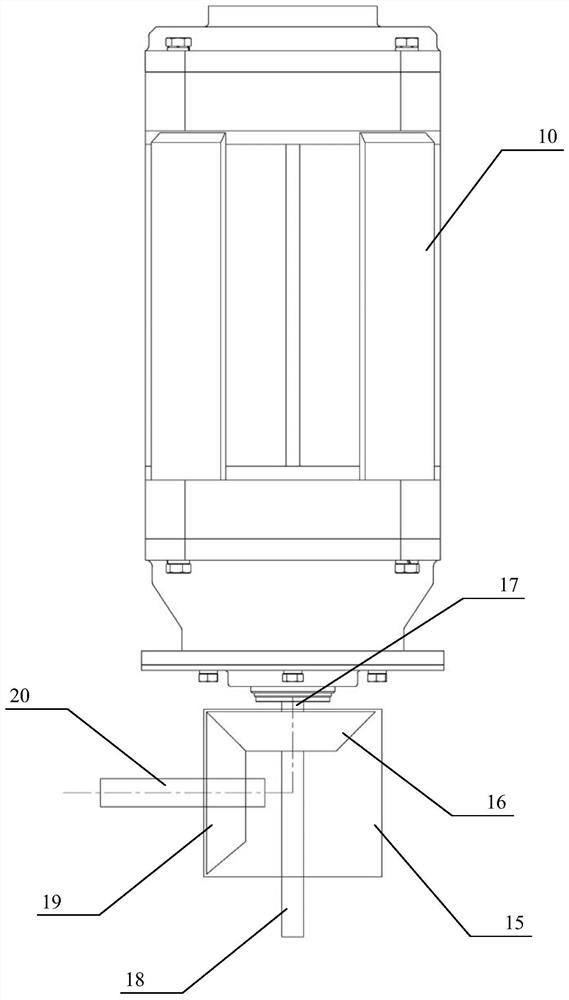
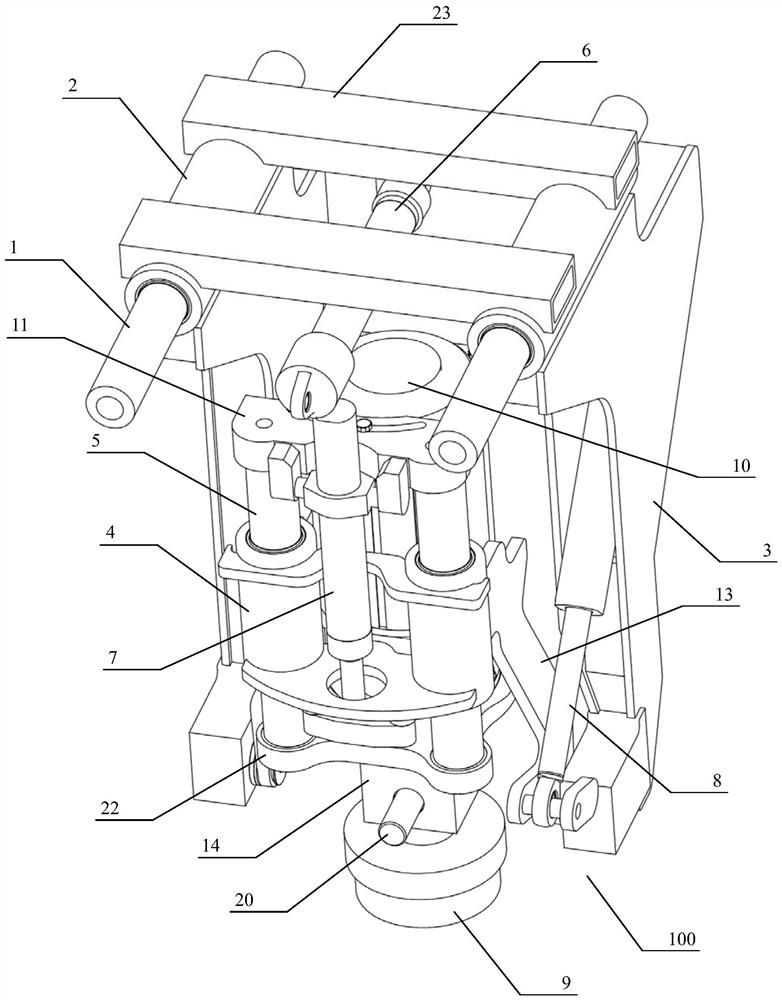
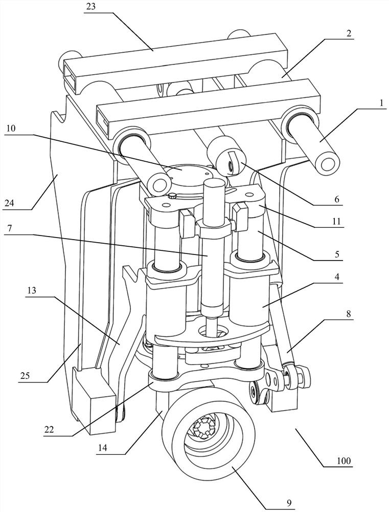
[0048] as attached figure 1 to attach Figure 5 As shown, this embodiment provides a comprehensive grinding unit for the inner side damage of the rail 40, especially for grinding the fat edge, an embodiment of the rail fat edge grinding unit 100 of the present invention, specifically comprising:

[0049] traverse mechanism;

[0050] Grinding motor 10, its output shaft links to each other with grinding wheel 9 through transmission mechanism 14, realizes the conversion of working state of grinding wheel 9 between axial grinding and tangential grinding through transmission mechanism 14;

[0051] It is used to install the grinding motor 10, and is movably connected to the grinding unit frame 3 of the traversing mechanism, and the traversing mechanism can drive the grinding motor 10 to realize the traversing operation;

[0052] The deflection mechanism connected between the grinding unit frame 3 and the grinding motor 10 can realize the deflection operation with the grinding moto...

Embodiment 2

[0063] as attached Figure 9 As shown, an embodiment of a rail grinding device 200 based on the rail fat edge grinding unit 100 shown in Embodiment 1 specifically includes:

[0064] The vehicle frame 300 arranged at the bottom of the rail grinding vehicle 400;

[0065] The traction mechanism 600 is installed between the vehicle frame 300 and the bottom of the vehicle body 500 of the rail grinding vehicle 400, and is used to transmit the traction force and drive the rail grinding unit 100 to perform grinding operations along the track;

[0066] And the rail grinding unit 100 installed on the vehicle frame 300, the rail fat edge grinding unit 100 can be configured as an end grinding unit or an arc grinding unit;

[0067] The end face grinding unit is used for targeted grinding of the fat edge on the inner side of the rail 40 , and the arc surface grinding unit is used for profile enveloping grinding of the rail 40 .

[0068]The rail grinding device 200 described in this embodi...

Embodiment 3

[0082] as attached Figure 10 As shown, an embodiment of the rail fat edge grinding unit 100 rail grinding vehicle 400 based on the rail fat edge grinding unit 100 described in embodiment 1 specifically includes:

[0083] Body 500;

[0084] And the rail grinding device 200 arranged at the lower part of the car body 500 .

[0085] Wherein, the traction mechanism 60 is installed on the bottom of the rail grinding vehicle 400 and connected with the vehicle frame 300 . One end of the lifting mechanism 70 is connected to the bottom of the rail grinding vehicle 400 , and the other end is connected to the vehicle frame 300 . The traction mechanism 60 and the lifting mechanism 70 both have one end connected to the bottom of the car body 500 of the rail grinding vehicle 400 and the other end connected to the vehicle frame 300 on which the rail grinding device 200 is installed. The traction mechanism 60 further adopts a vertical installation structure, which can solve the traction di...


PUM


Abstract

The invention discloses a steel rail fat edge grinding unit which comprises a transverse moving mechanism, a grinding motor, a grinding unit frame, a deflection mechanism and adownward pressing mechanism, wherein an output shaft of the grinding motor is connected with the grinding wheel through a transmission mechanism, and the grinding wheel is switched between the working state of axial grinding and the working state of tangential grinding through the transmission mechanism; the grinding unit frame is used for installing the grinding motor and is movably connected to the transverse moving mechanism, and the transverse moving mechanism can drive the grinding motor to achieve transverse moving operation; the deflection mechanism is connected between the grinding unit frame and the grinding motor, and the deflection mechanism can drive the grinding motor to achieve deflection operation; and the downward pressing mechanism is connected between the deflection mechanism and the polishing motor, and the polishing motor can be driven by the downward pressing mechanism to achieve lifting and downward pressing operation. The technical problems that an existing grinding device is single in strategy, the grinding mode cannot be adjusted according to actual needs, and the requirements for large grinding amount, removal of plastic fat edges of the steel rail and satisfaction of the profile and the surface roughness of the ground steel rail with the requirements can not be met at the same time can be solved.

Description

technical field [0001] The invention relates to the technical field of rail engineering machinery, in particular to a rail grinding unit aimed at grinding inner side damage of rails, especially fat edge grinding. Background technique [0002] As an important component of rail transit, rails are responsible for guiding vehicles to run in a specified direction, and transmitting the impact and load from vehicles to sleepers and fasteners. The strength and safety status of rails directly affect the smoothness and stability of rail transit vehicles. Safety. When subjected to heavy transportation pressure, the rail mainly bears the vertical stress, lateral stress and friction under the wheel load. Under the long-term action of complex stress, the profile of the rail will deteriorate greatly, and diseases such as fat edge and corrugation often appear. [0003] The grinding trolley is the executive mechanism of the grinding operation and the key component of the rail grinding trai...

Claims


Application Information

Patent Timeline
Patent Type & Authority Applications(China)
IPC IPC(8): E01B31/17
CPCE01B31/17
Inventor 赵宇晨罗旦郭平张东方余高翔李从祥王华杨全李雪辉
Owner ZHUZHOU TIMES ELECTRONICS TECH CO LTD
Why Eureka
Try Eureka