Paired-cylinder reverse-communication driving double-shaft swinging platform system
A platform and reverse technology, which is applied in the field of dual-axis swing platform system driven by reverse communication between cylinders, can solve the problems of small stiffness difference, asymmetric direct drive force of two cylinders, and difficulty in redundant drive control of multi-cylinder direct drive , to achieve the effect of improving the drive and structural force, increasing the anti-heavy and eccentric load capacity, and having a wide range of applications
- Summary
- Abstract
- Description
- Claims
- Application Information
AI Technical Summary
Problems solved by technology
Method used
Image
Examples
Embodiment 1
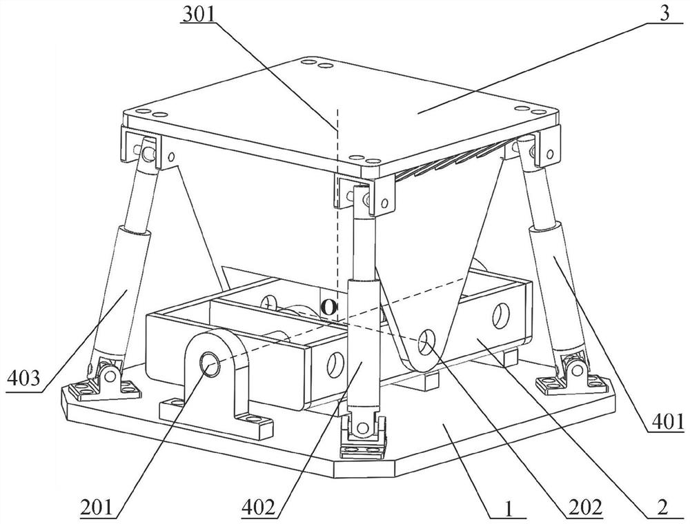
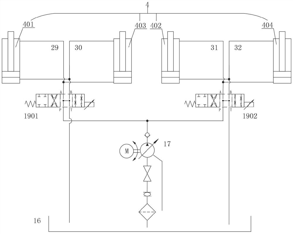
[0057] like figure 1 , figure 2 and Figure 10 As shown, when the working condition needs to compensate for transverse and longitudinal movement or need to provide lateral and longitudinal swing, first, the hydraulic oil pump 17 is supplied to the hydraulic oil into the tubing, the hydraulic oil from the reverse valve 21 passes through A The mouth, the p port of the first servo valve 1901, the hydraulic oil flows out from the A port of the first servo valve 1901, and the first oil pipe 29 enters the first driving cylinder 401 of the upper cavity and the lower chamber of the third drive cylinder 403, drive The cylinder rod movement, so that the lower chamber hydraulic oil of the first driving cylinder 401 and the upper cavity hydraulic oil of the third drive cylinder 403, passes through the second oil tube 30 into the first servo valve 1901, from the T of the first servo valve 1901 The mouth flows into the fuel tank. At this time, the first oil pipe 29 is an intake pipe. The second ...
Embodiment 2
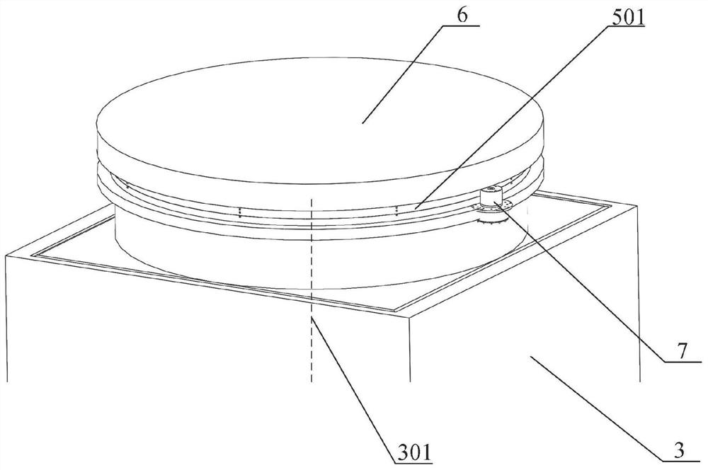
[0061] like image 3 As shown, when the working condition needs to compensate for cross-shaking and longitudinal movement or need to provide lateral and longitudinal swing, it is necessary to return to the gallowthrough, first, the upper end of the rocking platform 3 is mounted with a third rotation sub-501, and install the rotary platform 6 At the upper end of the third rotation sub 501, the rotary driver 7 is mounted on the third rotation sub-501 side, and the rotary driver 7 drives the third rotation sub-501 to rotate and drive the rotary platform 6 rotation, the third rotation sub-501 axis and the swing platform 3 method The center line 301 is coincident; at this time, the movement of the rocking platform 3 and the lower flush frame 2 and the hydraulic system operation are the same as in Example 1, and at this time, the moving platform can have three degrees of freedom.
Embodiment 3
[0063] like Figure 4 As shown, when the working conditions need to compensate for horizontal and longitudinal movement or need to provide lateral and longitudinal swing, it is necessary to compensate for elevation motion or provide lifting motion, first, the swing platform 3 is a hollow cylindrical shape, a swing platform 3 internal loading There is a lifting column 8 and a linear driver 9, and the lifting column 8 is constituted by the first moving sub 302. The first moving sub 301 direction is parallel to the swing platform 3 method, and the linear driver 9 drives the rose post 8 The rocking platform 3 is lifted, and the upper end of the upper end of the lifting column 8 is connected to the upper end of the line driver 9, and the lower end of the linear driver 9 is connected to the bottom plate of the lower end plate 2, the axis of the linear driver 9 and the rocking platform 3 method The movement to the center line 301; at this time, the movement of the rocking platform 3 and t...
PUM
 Abstract
Description
Claims
Application Information
 - R&D
- Intellectual Property
- Life Sciences
- Materials
- Tech Scout
- Unparalleled Data Quality
- Higher Quality Content
- 60% Fewer Hallucinations
Browse by: Latest US Patents, China's latest patents, Technical Efficacy Thesaurus, Application Domain, Technology Topic, Popular Technical Reports.
© 2025 PatSnap. All rights reserved.Legal|Privacy policy|Modern Slavery Act Transparency Statement|Sitemap|About US| Contact US: help@patsnap.com


