A lighting adjustment system
A light adjustment and cavity adjustment technology, which is applied in the field of auto parts, can solve the problems of complex structure of the light adjustment system, high manufacturing cost, and single adjustment direction, and reduce the risk of missing adjustment ball heads or adjustment ball cards. The effect of saving parts cost and simple structure composition
Active Publication Date: 2022-06-03
DONGFENG MOTOR GRP
View PDF10 Cites 0 Cited by
- Summary
- Abstract
- Description
- Claims
- Application Information
AI Technical Summary
Problems solved by technology
[0006] The embodiment of the present application provides a lighting adjustment system to solve the problems in the related art that the lighting adjustment system has a complex structure, high manufacturing cost, and single adjustment direction, resulting in poor versatility
Method used
View moreImage
Smart ImageViewing Examples
Examples
Embodiment Construction
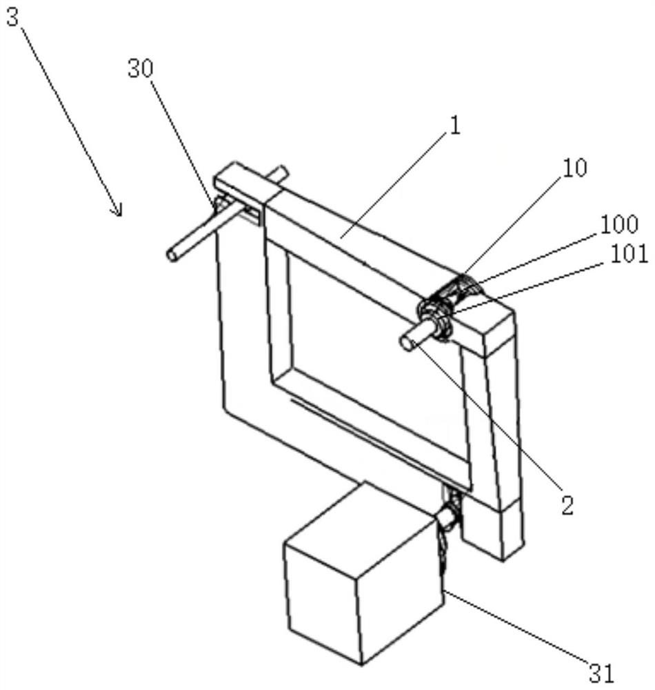
[0037] Further, a spherical hinge pair 102 is provided in the described receiving cavity 100.
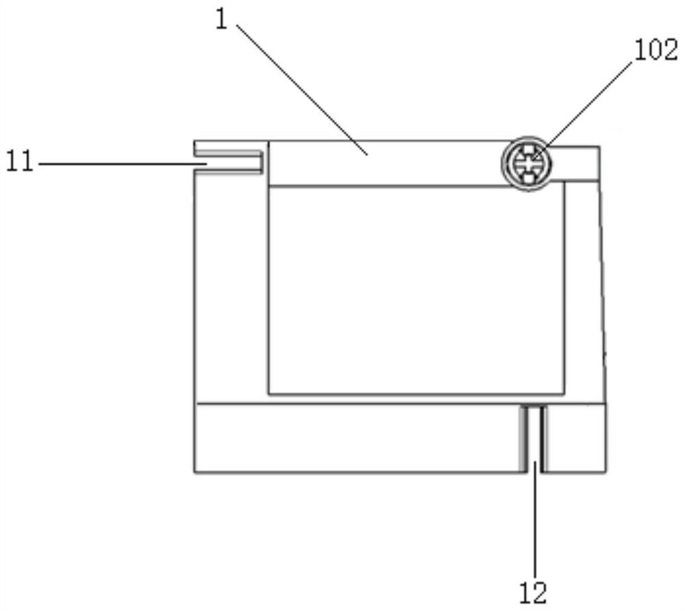
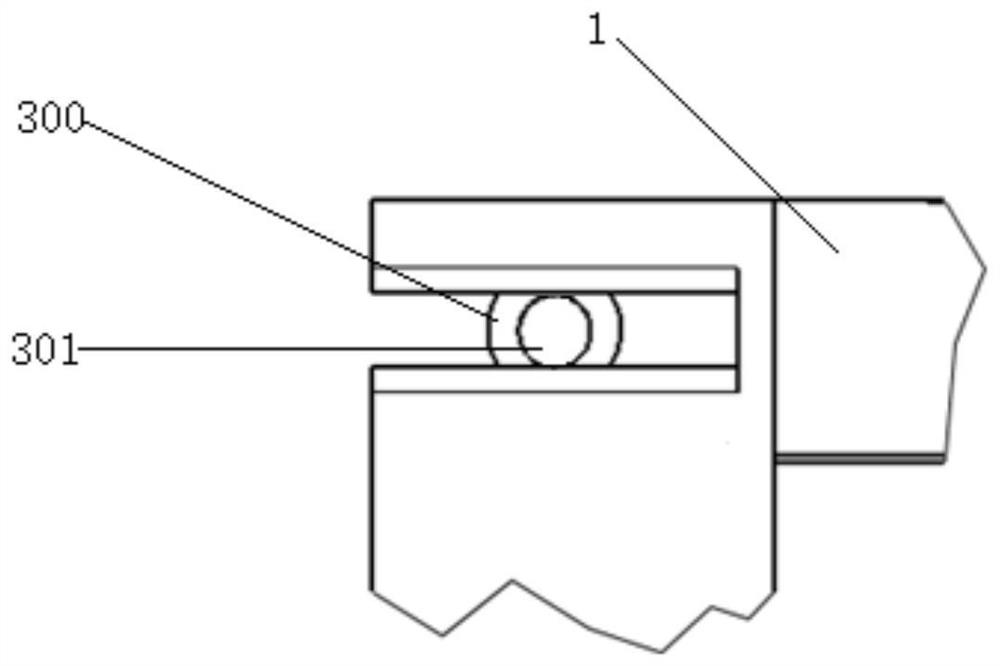
[0040] Further, as shown in FIG. 3, the adjustment frame body 1 is also provided with a first adjustment cavity 11, and the first adjustment cavity
[0042] Further, as shown in FIG. 5, the adjustment frame body 1 is also provided with a second adjustment cavity 12, and the second adjustment cavity
Login to View More PUM
 Abstract
The application relates to a lighting adjustment system, and relates to the technical field of auto parts. The lighting adjustment system includes an adjustment frame and an adjustment unit. An adjustment head is arranged on the adjustment frame. One end of the adjustment head is connected to the adjustment frame, and the other end is used to connect with the lamp body. The lamp body and the adjustment frame are used to fix the light source module. The adjustment unit includes a first adjustment module and a second adjustment module. The first adjustment module and the second adjustment module are separately arranged on the adjustment frame. The second adjustment module is used to drive the adjustment frame to rotate within a second preset angle around the horizontal axis of the adjustment head after driving the adjustment frame to rotate within a first preset angle around the vertical axis where the adjustment head is located. The lighting adjustment system provided by the present application solves the problems in the related art that the lighting adjustment system has a complex structure, high manufacturing cost, and single adjustment direction, resulting in poor versatility.
Description
A light adjustment system technical field [0001] The application relates to the technical field of auto parts, in particular to a lighting adjustment system. Background technique With the increasing popularity of automobiles, traffic safety has become a top priority that needs to be solved at present, so More and more electronic products are used in the driving process, such as the anti-lock braking system ABS (Anti-lock Break System), electronic brake force distribution EBD (Electronic Brakeforce Distribution), driving anti-skid System ASR (Acceleration Slip Regulation) and so on, these auxiliary systems have greatly improved the driving ability of the car. safety. The premise that the above-mentioned auxiliary system can exert its effect well is that the driver has a good visual environment. When the weather conditions are good, the driver has a good understanding of the driving road and can take appropriate countermeasures in time. At night, however, the dri...
Claims
Login to View More Application Information
Patent Timeline
 Patent Type & Authority Patents(China)
IPC IPC(8): F21S41/657F21V21/15B60Q1/068F21W102/00
CPCF21S41/657F21V21/15B60Q1/068F21W2102/00
Inventor 邓培刘凤王小兰田彬彬廖朋
Owner DONGFENG MOTOR GRP
Features
- R&D
- Intellectual Property
- Life Sciences
- Materials
- Tech Scout
- Unparalleled Data Quality
- Higher Quality Content
- 60% Fewer Hallucinations
Learn More Browse by: Latest US Patents, China's latest patents, Technical Efficacy Thesaurus, Application Domain, Technology Topic, Popular Technical Reports.
© 2025 PatSnap. All rights reserved.Legal|Privacy policy|Modern Slavery Act Transparency Statement|Sitemap|About US| Contact US: help@patsnap.com


