
Mark point matching method and device, computer equipment and storage medium

A technology of matching method and mark point method, which is applied in the field of laser scanning, can solve the problems of high time complexity and achieve the effect of reducing time complexity and simplifying matching problems

Pending Publication Date: 2021-08-06
SHENZHEN SHUMA ELECTRONICS TECH
View PDF0 Cites 6 Cited by
  • Summary
  • Abstract
  • Description
  • Claims
  • Application Information

AI Technical Summary

Problems solved by technology

The traditional matching method of landmark points directly uses triangle congruence to filter out accurate matching points, and then determines the best transformation relationship according to other inspection attributes, while the traditional matching method of landmark points has the problem of high time complexity

Method used


Image

  • Mark point matching method and device, computer equipment and storage medium
  • Mark point matching method and device, computer equipment and storage medium
  • Mark point matching method and device, computer equipment and storage medium

Examples


Embodiment Construction

[0032] It should be understood that the specific embodiments described here are only used to explain the present invention, not to limit the present invention.

[0033] The following will clearly and completely describe the technical solutions in the embodiments of the present invention with reference to the accompanying drawings in the embodiments of the present invention. Obviously, the described embodiments are only part of the embodiments of the present invention, not all of them. Based on the embodiments of the present invention, all other embodiments obtained by persons of ordinary skill in the art without making creative efforts belong to the protection scope of the present invention.

[0034] It should be noted that all directional indications (such as up, down, left, right, front, back...) in the embodiments of the present invention are only used to explain the relationship between the components in a certain posture (as shown in the figure). If the specific posture c...


PUM


Abstract

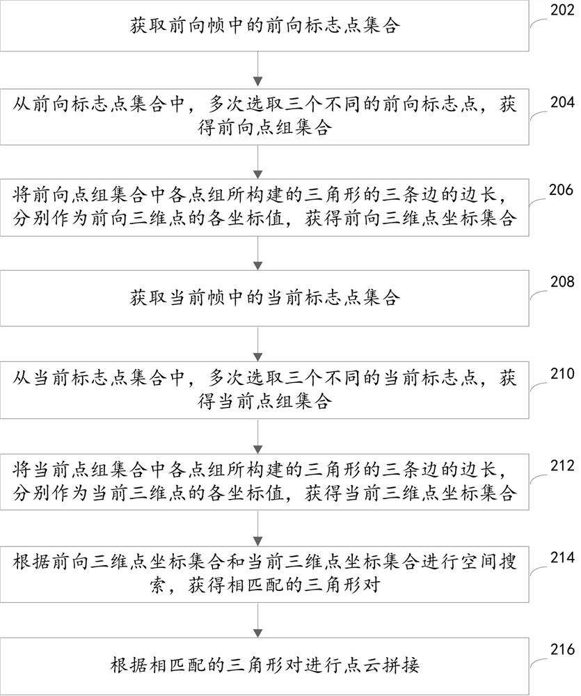
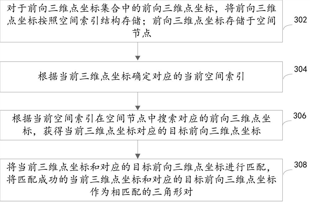
The invention relates to a mark point matching method and device, computer equipment and a storage medium, and the method comprises the steps: selecting different mark points from a mark point set for multiple times, taking the three side lengths of a constructed triangle as the coordinate values of a three-dimensional point, carrying out the space search based on the three-dimensional point, and obtaining a matched triangle pair, point cloud splicing is realized; the three sides of the triangle are converted into three points, so that the complex triangle matching problem can be simplified in combination with a spatial search mode, and the time complexity is reduced.

Description

technical field [0001] The present invention relates to the technical field of laser scanning, in particular to a marking point matching method, device, computer equipment and storage medium. Background technique [0002] In laser real-time 3D scanning, point cloud images from different perspectives are finally spliced ​​together, so it is very important to track and calculate the positional relationship of point clouds. The current 3D scanning should generally use reflective marker points for positioning. The principle is that under different viewing angles, the 3D positions corresponding to the marker points are completely different, and the topological relationship between the marker points does not change. Therefore, using this principle, by transforming The relative positional relationship between handheld scanning instruments at different viewing angles can be obtained, so that point clouds from different viewing angles can be successfully spliced. The traditional mat...

Claims


Application Information

Patent Timeline
IPC IPC(8): G06T7/70G06T17/00
CPCG06T7/70G06T17/005G06T2207/10028
Inventor 杨琪冉国江翟剑坤
Owner SHENZHEN SHUMA ELECTRONICS TECH
Learn More