

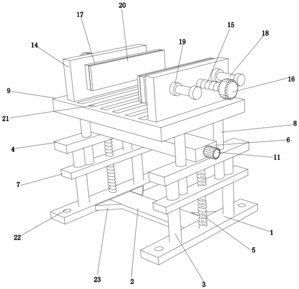
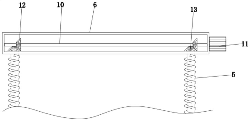
New energy vehicle charging pile mounting structure
A new energy vehicle and installation structure technology, applied in the direction of electric vehicle charging technology, charging stations, electric vehicles, etc., can solve the problems of charging pile damage, long installation and construction period, unfavorable charging pile quick disassembly and assembly, etc., to achieve easy circulation Utilization, not easy to soak in water, easy to disassemble and assemble
- Summary
- Abstract
- Description
- Claims
- Application Information
AI Technical Summary
Problems solved by technology
Method used
Image

Examples
Embodiment Construction
[0016] The present invention will be described in further detail below in conjunction with the accompanying drawings.
[0017] The specific implementation manner of the present invention will be further described below in conjunction with the accompanying drawings. Wherein the same components are denoted by the same reference numerals.
[0018] It should be noted that the words "front", "rear", "left", "right", "upper" and "lower" used in the following description refer to the directions in the drawings, and the words "inner" and "outer ” refer to directions towards or away from the geometric center of a particular part, respectively.
[0019] In order to make the content of the present invention more clearly understood, the technical solutions in the embodiments of the present invention will be clearly and completely described below in conjunction with the drawings in the embodiments of the present invention.
[0020] In conjunction with the accompanying drawings, a new ene...
PUM
 Abstract
Description
Claims
Application Information