Municipal engineering groove garbage cleaning equipment
A technology for garbage cleaning and engineering ditches, which can be used in water conservancy projects, cleaning of open water surfaces, construction, etc., and can solve problems such as slow speed
- Summary
- Abstract
- Description
- Claims
- Application Information
AI Technical Summary
Problems solved by technology
Method used
Image

Examples
Embodiment 1
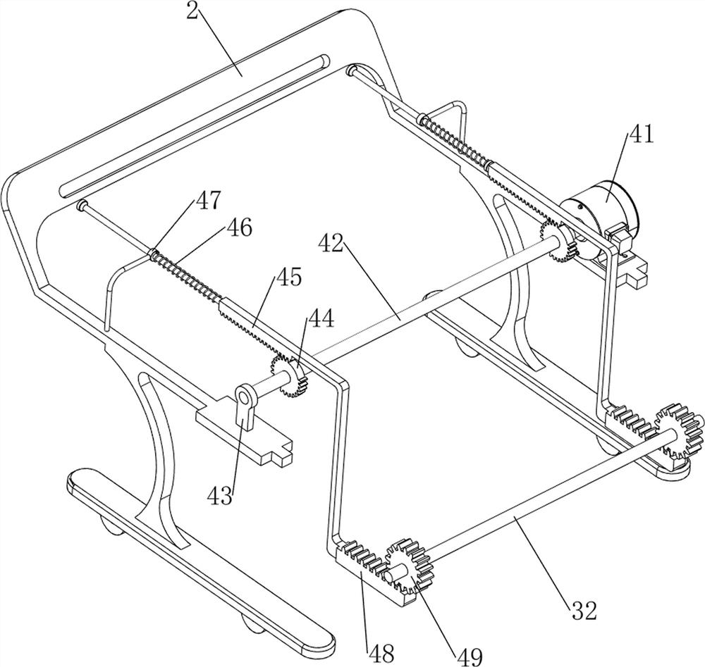
[0028] A municipal engineering ditch garbage cleaning equipment, such as figure 1 As shown, it includes a tire 1, a support frame 2, a manual cleaning mechanism 3 and an automatic cleaning mechanism 4. The bottom of the support frame 2 is rotatably provided with four tires 1, and the front side of the support frame 2 is provided with a manual cleaning mechanism 3. 2 is provided with automatic cleaning mechanism 4.
[0029] When the user needs to clean the groove, the device can be used. First, with the cooperation of the tire 1, the user can push the device to the position where it needs to be cleaned, and the automatic cleaning mechanism 4 drives the parts of the manual cleaning mechanism 3. After the cleaning is completed, the device can be removed.
Embodiment 2
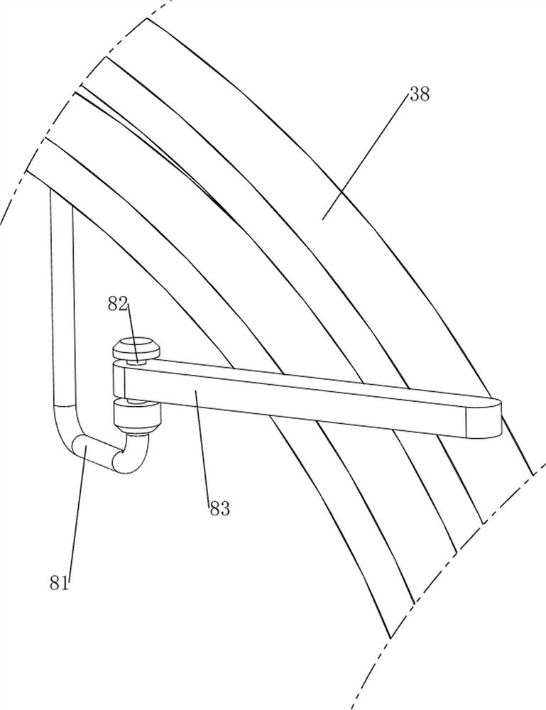
[0031] On the basis of Example 1, such as Figure 2-4 As shown, the manual cleaning mechanism 3 includes a first fixed column 31, a first rotating shaft 32, a first connecting rod 33, a second connecting rod 34, a first linear spring 35, a baffle plate 36, a slide block 37 and a special-shaped slide rail 38. The front side of the support frame 2 is symmetrically provided with a first fixed column 31, and a first rotating shaft 32 is provided for rotation between the first fixed columns 31, and four first connecting rods 33 are provided on the lower side of the first rotating shaft 32. The bottom of the first connecting rod 33 is slidably provided with a second connecting rod 34, two first linear springs 35 are connected between the second connecting rod 34 and the first connecting rod 33, and the front side of the first connecting rod 33 is provided with a stopper. Plate 36 is connected with slide block 37 on the first connecting rod 33 on left and right sides, and support fra...
Embodiment 3
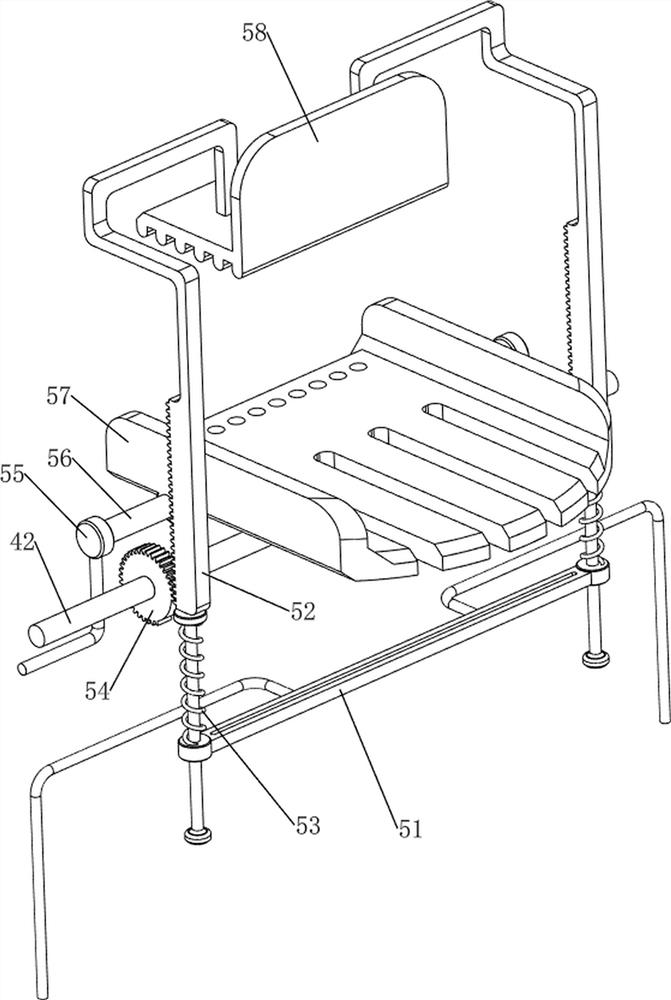
[0036] On the basis of Example 2, such as Figure 5-9 Shown, also include extruding mechanism 5, extruding mechanism 5 includes the 4th fixed post 51, the 3rd rack 52, the 3rd linear spring 53, the 2nd missing gear 54, the 5th fixed post 55, the 3rd rotating shaft 56. The first supporting plate 57 and the pressure plate 58, the fourth fixed column 51 is arranged in the middle of the support frame 2, and two third racks 52 are slidably arranged on the fourth fixed column 51, and the third rack 52 is connected with the fourth fixed column. A third linear spring 53 is connected between the columns 51, a pressing plate 58 is connected between the third racks 52 on both sides, and two second missing gears 54 are arranged on the second rotating shaft 42, and the second missing gear 54 and the third The racks 52 are meshed, and the middle of the support frame 2 is symmetrically provided with a fifth fixed column 55 , and a third rotating shaft 56 is provided rotatably between the fif...
PUM
 Abstract
Description
Claims
Application Information
 - R&D
- Intellectual Property
- Life Sciences
- Materials
- Tech Scout
- Unparalleled Data Quality
- Higher Quality Content
- 60% Fewer Hallucinations
Browse by: Latest US Patents, China's latest patents, Technical Efficacy Thesaurus, Application Domain, Technology Topic, Popular Technical Reports.
© 2025 PatSnap. All rights reserved.Legal|Privacy policy|Modern Slavery Act Transparency Statement|Sitemap|About US| Contact US: help@patsnap.com