
Metal part fracture machine, connecting rod fracture machine, metal part fracture method, connecting rod fracture method, method for manufacturing metal part, and method for manufacturing connecting rod

A technology of metal parts and components, applied in the direction of connecting rods, metal processing, shafts and bearings, etc., can solve the problem of not being able to obtain fracture surfaces, and achieve the effect of suppressing excessive stress

Pending Publication Date: 2021-08-13
ERNST & YOUNG
View PDF9 Cites 0 Cited by
  • Summary
  • Abstract
  • Description
  • Claims
  • Application Information

AI Technical Summary

Problems solved by technology

Therefore, sometimes the fracture surface is curved or inclined and cracked, and a good fracture surface cannot be obtained.

Method used


Image

  • Metal part fracture machine, connecting rod fracture machine, metal part fracture method, connecting rod fracture method, method for manufacturing metal part, and method for manufacturing connecting rod
  • Metal part fracture machine, connecting rod fracture machine, metal part fracture method, connecting rod fracture method, method for manufacturing metal part, and method for manufacturing connecting rod
  • Metal part fracture machine, connecting rod fracture machine, metal part fracture method, connecting rod fracture method, method for manufacturing metal part, and method for manufacturing connecting rod

Examples


Embodiment Construction

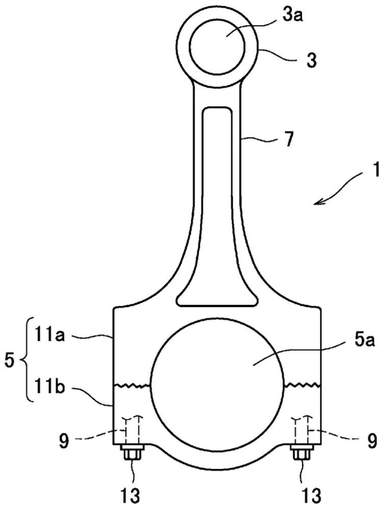
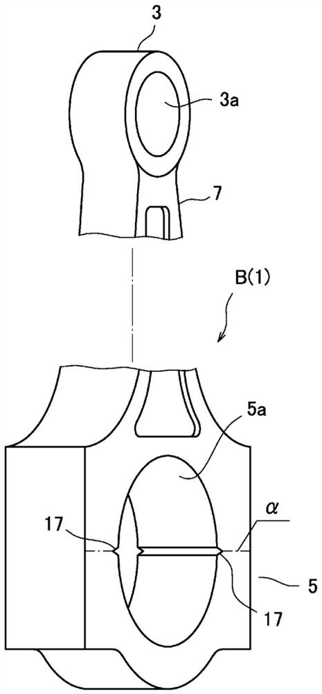
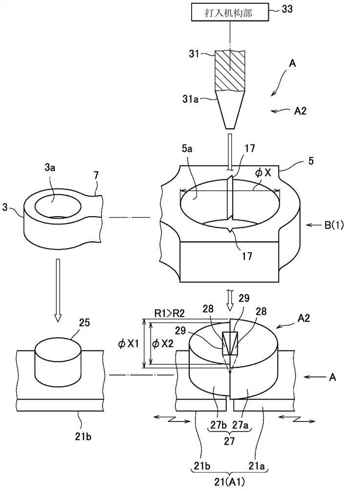
[0066] Below, based on Figure 1 to Figure 6 An embodiment is shown to illustrate the invention.

[0067] figure 1 A front view of a link 1 (hereinafter referred to as link 1 ) as a product is shown. In addition, the connecting rod 1 is a metal member constituting a general vehicle engine.

[0068] The connecting rod 1 has: a small end portion 3 having a piston pin hole 3a; a large end portion 5 having a crank pin hole 5a (equivalent to the through hole in the present application); and a rod 7 connecting the small end portion 3 and the large end portion 5. In addition, the large end portion 5 is provided with a pair of bolt holes 9 located on the sides of the crank pin hole 5a.

[0069] The large end portion 5 is divided into a main body portion 11 a on the rod side and a semicircular cover portion 11 b on the cover side so as to sandwich a crank pin (not shown). That is, the connecting rod 1 is a member that fastens the main body portion 11 a and the cover portion 11 b b...


PUM


Abstract

Using, as a half-split type mandrel 27 to be inserted into a through-hole 5a of a metal part and a connecting rod B, a semi-circular first mandrel 27a that comes into contact with a side surface of the through-hole having rigidity on the lower side and corresponds to the diameter of the through-hole and a semi-circular second mandrel 27b that comes into contact with a side surface of the though-hole having rigidity on the higher side and that has a radial dimension smaller than the first mandrel member, a correction for making the rigidity close to isotropic is performed and a crack that occurs in the metal part and the connecting rod is propagated along a target fracture surface alpha during fracturing.

Description

technical field [0001] The present invention relates to a breaking device for a metal part, a breaking device for a connecting rod, a method for breaking a metal part, a method for breaking a connecting rod, a method for manufacturing a metal part, and a method for manufacturing a connecting rod. Background technique [0002] Among metal parts having through-holes, parts cut in half by breaking through the through-holes may be combined and used as a pair of products. A connecting rod (connecting rod) (hereinafter referred to as a connecting rod) is known as a representative example of such a broken and combined metal member. [0003] This method is mostly used to break the connecting rod from the large end. In the manufacture of this connecting rod, a split-type mandrel is inserted into the through-hole of the big end, and a load is applied to the mandrel in a direction in which the mandrel expands relative to the through-hole, so that the big end is aligned with the cover ...

Claims


Application Information

Patent Timeline
IPC IPC(8): B26F3/02F16C7/00B23P13/00
CPCF16C7/02F16C7/00B23P2700/04B23P15/00
Inventor 长谷浩一村田岳人松井淳悟
Owner ERNST & YOUNG
Learn More