
Toroidal infinitely variable transmission

a transmission and infinitely variable technology, applied in the direction of friction gearings, gearing elements, gearings, etc., can solve the problems of deterioration of transmission efficiency or durability, reduce production costs and labor hours involved in shaft fabrication, reduce production costs, and reduce production costs

Inactive Publication Date: 2016-06-23
NSK LTD
View PDF2 Cites 3 Cited by
  • Summary
  • Abstract
  • Description
  • Claims
  • Application Information

AI Technical Summary

Benefits of technology

This patent invention can reduce the cost and labor required to create a shaft, prevent the shaft from getting longer in length, and prevent excessive stress from occurring at the oil hole.

Problems solved by technology

In the case of only the loading cam type pressing unit 12 being employed, a thrust force (a pressing force of the input disc) is generated which is proportional only to the inputted torque, and therefore, depending upon a gear ratio, an excessive pressing force is exerted on the contact portion between the disc and the roller, leading to fears that the transmission efficiency is deteriorated or the durability is deteriorated.

Method used


Image

  • Toroidal infinitely variable transmission
  • Toroidal infinitely variable transmission
  • Toroidal infinitely variable transmission

Examples


first embodiment

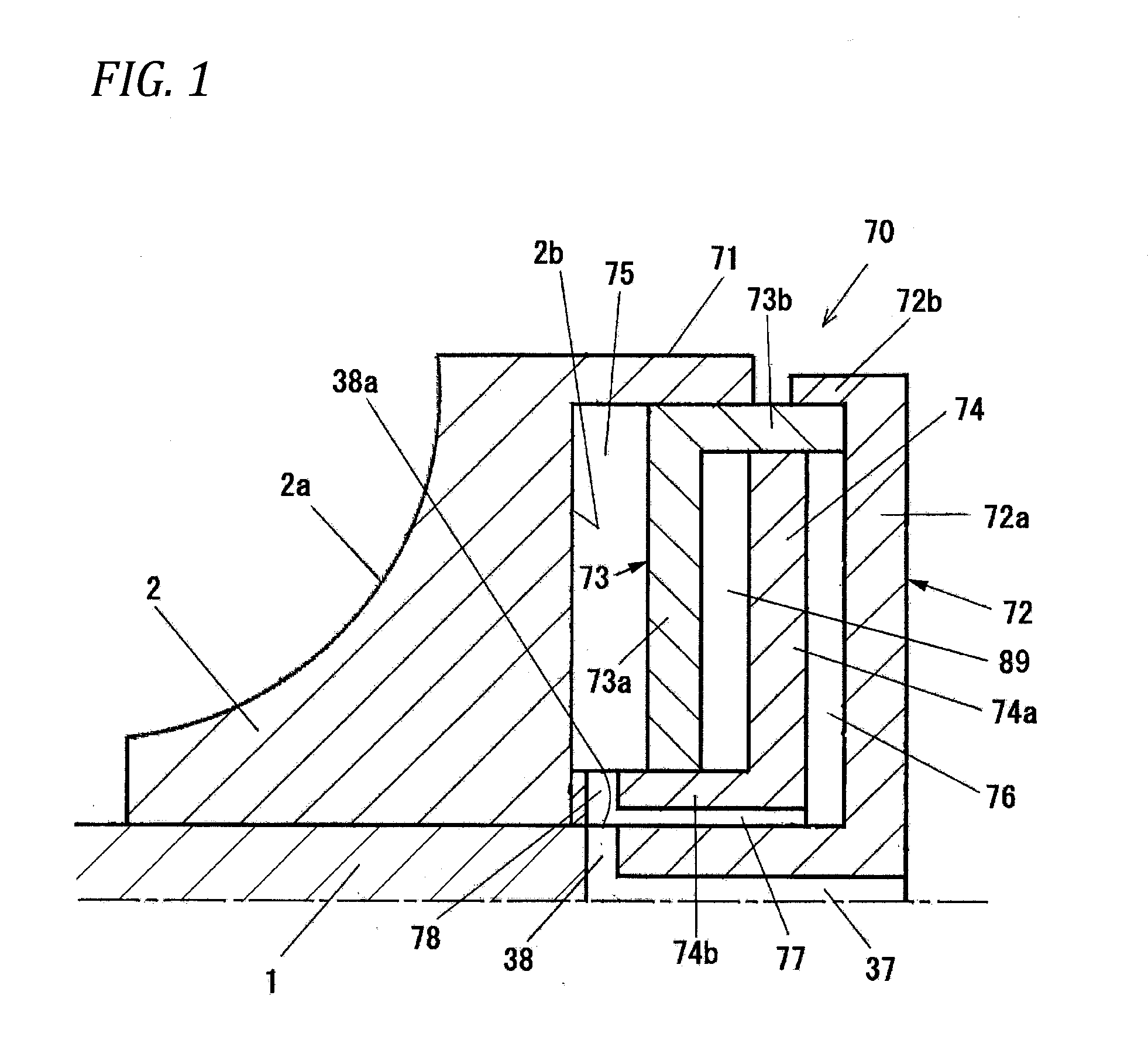
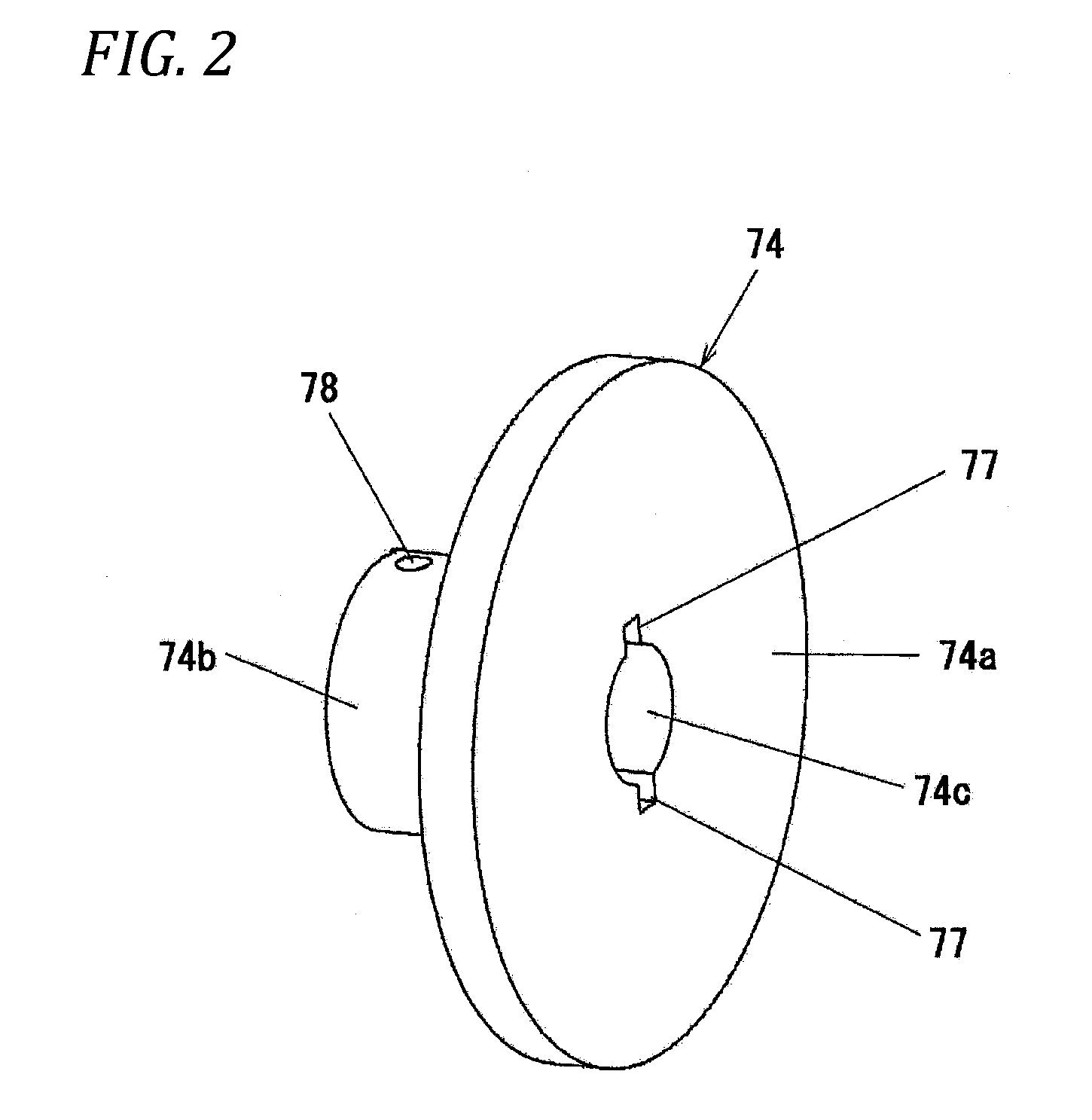
[0056]FIG. 1 shows a half sectional view of a main part (a peripheral portion of a pressing unit) of a toroidal infinitely variable transmission according to a first embodiment of the invention. The toroidal infinitely variable transmission according to this embodiment is a so-called double cavity type high torque toroidal infinitely variable transmission and is made up of two input discs 2 and two output discs (refer to FIG. 3) which are mounted on an outer circumference of an input shaft (a shaft) 1 (in FIG. 1, only an input disc (a first disc) 2 is shown which lies on an input side into which power is inputted from an engine (a prime mover)). A power roller is held between the input disc 2 and the output disc (a second disc), and this power roller transmits a rotational force of the input disc 2 to the output disc at a predetermined gear ratio. As with a conventional configuration shown in FIG. 5, an output gearwheel is supported rotatably on an outer circumference of a middle po...

second embodiment

[0079]FIG. 3 is a half sectional view of a main part (a peripheral portion of a pressing unit) of a toroidal infinitely variable transmission according to a second embodiment of the invention, and FIG. 4 is a sectional view taken along a line A-A in FIG. 3. The toroidal infinitely variable transmission according to this embodiment is a double cavity type high torque toroidal infinitely variable transmission similar to that of the first embodiment. This embodiment differs from the first embodiment only in the configuration of a pressing unit 80. Hereinafter, the different feature will be described while imparting like reference numerals to constituent portions of the second embodiment which are common for those of the first embodiment, so that the description thereof will be omitted or simplified.

[0080]A pressing unit 80 is provided on a back surface 2b of an input disc 2 (an input disc 2 shown in FIG. 3) which is positioned at an input side of an input shaft (shaft) 1, and this pres...


PUM


Abstract

A hydraulic pressing unit for pressing an input disc in an axial direction includes a first hydraulic pressure chamber and a second hydraulic pressure chamber, a primary piston facing the first hydraulic pressure chamber and a secondary piston facing the second hydraulic pressure chamber, and oil holes configured to supply oil into the first hydraulic pressure chamber are formed in an input shaft, while oil paths configured to supply oil into the second hydraulic pressure chamber are formed in the secondary piston. Consequently, a separate oil hole configured to supply oil into the second hydraulic pressure chamber is not formed in the input shaft. Thus, it is possible to mitigate the cost and labor hours involved in fabrication of the input shaft. Two oil holes spaced apart from each other in an axial direction do not exist in the input shaft.

Description

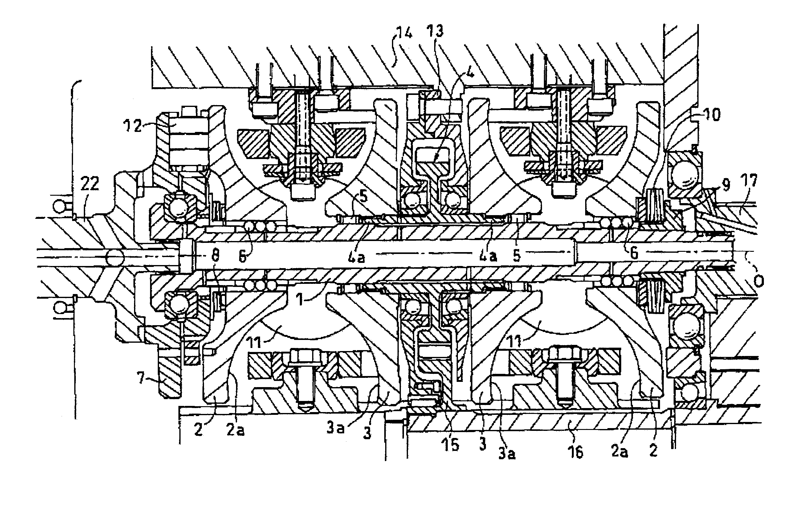
TECHNICAL FIELD[0001]The present invention relates to a toroidal infinitely variable transmission which can be applied to transmissions for motor vehicles and various industrial machines.BACKGROUND ART[0002]FIG. 5 shows an example of a conventional toroidal infinitely variable transmission which can be made use of as a motor vehicle transmission. This toroidal infinitely variable transmission is a so-called double cavity, high torque toroidal infinitely variable transmission which is made up of two input discs 2, 2 and two output discs 3, 3 which are mounted on an outer circumference of an input shaft 1. Additionally, an output gearwheel 4 is supported rotatably on an outer circumference of a middle portion of the input shaft 1. The output discs 3, 3 are connected through spline engagement to cylindrical flange portions 4a, 4a which are provided at a central portion of the output gearwheel 4.[0003]The input shaft 1 is driven to rotate via a pressing unit 12 by a drive shaft 22 of an...

Claims


Application Information

Patent Timeline
Patent Type & Authority Applications(United States)
IPC IPC(8): F16H15/38F16H63/06
CPCF16H63/065F16H15/38
Inventor KITA, MASAHIROOISHI, YASUNORINISHII, HIROKI
Owner NSK LTD
Learn More