Eureka AIR delivers breakthrough ideas for toughest innovation challenges, trusted by R&D personnel around the world.

Fixing structure of engine cover supporting rod and vehicle

A technology for fixing the structure and the engine cover, applied in the field of vehicle parts, can solve the problems of laborious, scratching, and safety hazards in pulling out the strut, and achieve the effect of pulling out labor-saving

Active Publication Date: 2021-08-17
CHERY AUTOMOBILE CO LTD
View PDF10 Cites 0 Cited by
  • Summary
  • Abstract
  • Description
  • Claims
  • Application Information

AI Technical Summary

Problems solved by technology

Since there is no fulcrum for the hand pulling out the strut when pulling out the strut, it is more laborious for the user to pull out the strut. When the strut is not well controlled, it is easy to cause the strut to rub against the engine cover or other parts of the front cabin of the vehicle; in addition, because a large force is required to pull out the strut, sometimes the snap slot of the buckle will break and fail. Furthermore, the strut has no fixed structure inside the front cabin of the vehicle and is in a free state, resulting in the strut shaking everywhere during driving, which poses a certain safety hazard

Method used


Image

  • Fixing structure of engine cover supporting rod and vehicle
  • Fixing structure of engine cover supporting rod and vehicle
  • Fixing structure of engine cover supporting rod and vehicle

Examples


Embodiment Construction

[0064] The following will clearly and completely describe the technical solutions in the embodiments of the present application with reference to the drawings in the embodiments of the present application. Obviously, the described embodiments are part of the embodiments of the present application, not all of them. Based on the embodiments in this application, all other embodiments obtained by persons of ordinary skill in the art without making creative efforts belong to the scope of protection of this application.

[0065] Before the implementation of the present application is further described in detail, the orientation nouns involved in the embodiments of the present application are based on the orientation shown in the figure, and are only used to clearly describe the well completion stimulation device in the embodiment of the present application, and do not It has the significance of limiting the protection scope of the present application.

[0066] The embodiments of the...


PUM


Abstract

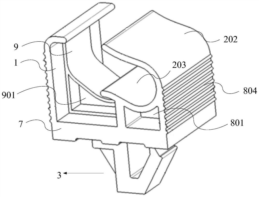
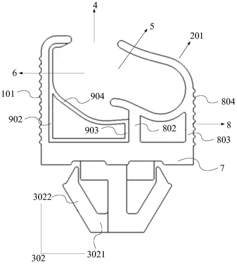
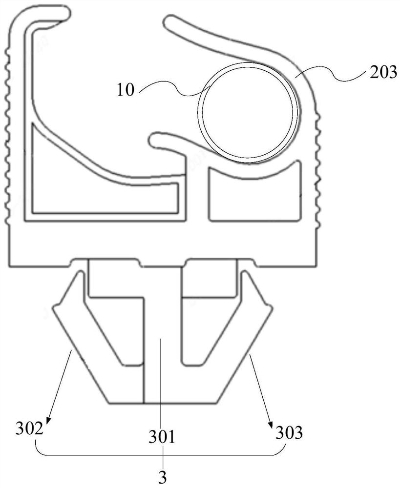
The invention discloses a fixing structure of an engine cover supporting rod and a vehicle, and belongs to the technical field of vehicle parts. The structure comprises a supporting plate and a clamping mechanism, wherein a first opening which is opened upwards is formed between the supporting plate and the clamping mechanism; a clamping groove is formed in the clamping mechanism, the clamping groove is suitable for clamping the engine cover supporting rod, and a second opening is formed in the side, which faces the supporting plate, of the clamping groove; the second opening is communicated with the first opening, a channel allowing the engine cover supporting rod to pass through is formed between the second opening and the first opening, the clamping groove and the channel are in a through state in the first direction, and the first direction is the length direction of the engine cover supporting rod located in the clamping groove. By means of the structure, the engine cover supporting rod can be fixed, and labor can be saved when a user pulls out the engine cover supporting rod.

Description

technical field [0001] The invention relates to the technical field of vehicle parts, in particular to a fixing structure of an engine cover strut and a vehicle. Background technique [0002] During the use of the vehicle, it is often necessary to open the engine cover. When the user performs the operation of opening the engine cover, he usually first uses the engine switch in the cab to open the engine cover, then pulls the safety buckle of the engine cover, then pulls out the engine cover support rod from the fixed position, and finally pulls the engine cover support rod This is done by snapping the top end of the lever into place on the hood and extending the hood fully. [0003] In the related art, the structure for fixing the engine cover strut is generally a single arc-shaped fixing buckle, and when the strut is snapped into the arc-shaped space, the fixing can be realized. [0004] In the process of realizing the present invention, the inventors found that this rela...

Claims


Application Information

Patent Timeline
Patent Type & Authority Applications(China)
IPC IPC(8): B62D25/12
CPCB62D25/12
Inventor 肖洪波魏伟高庆利
Owner CHERY AUTOMOBILE CO LTD
Why Eureka
Eureka Blog
Learn More