Engine system control method, control device and engine system

An engine system and control method technology, applied in the direction of engine components, machines/engines, mechanical equipment, etc., can solve the problems of engine fire, failure to timely reflect the lubrication state of the supercharger, damage to the rotor system, etc.

Active Publication Date: 2022-04-15
HUNAN DEUTZ POWER CO LTD
View PDF15 Cites 0 Cited by
  • Summary
  • Abstract
  • Description
  • Claims
  • Application Information

AI Technical Summary

Problems solved by technology

However, when the supercharger fails, the rotor system of the supercharger is damaged and the sealing system fails. At this time, the lubricating oil can still be cooled through the supercharger, resulting in the lag of the temperature change of the coolant, which cannot reflect the supercharger in time. Changes in the lubrication state lead to large fault detection errors, and even cause engine fire faults

Method used


Image

  • Engine system control method, control device and engine system
  • Engine system control method, control device and engine system
  • Engine system control method, control device and engine system

Examples


Embodiment 1

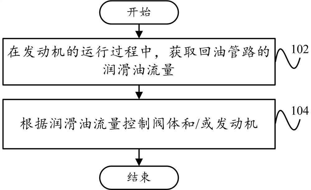
[0049] Such as figure 1 As shown, according to the embodiment of the first aspect of the present invention, a control method of an engine system is proposed, including:

[0050] Step 102, during the running of the engine, obtain the lubricating oil flow of the oil return line;

[0051] Step 104, controlling the valve body and / or the engine according to the lubricating oil flow.

[0052] In this embodiment, due to failure of the supercharger, such as abnormal wear of the supercharger bearing, broken shaft of the supercharger and failure of the seal ring of the supercharger, the amount of lubricating oil passing through the supercharger will be far greater than The amount of lubricating oil in normal operation. For this reason, during the operation of the engine, the lubricating oil flow of the oil return line of the engine system is periodically obtained, and it is judged whether the supercharger is faulty according to the lubricating oil flow, and the valve body and / or the e...

Embodiment 2

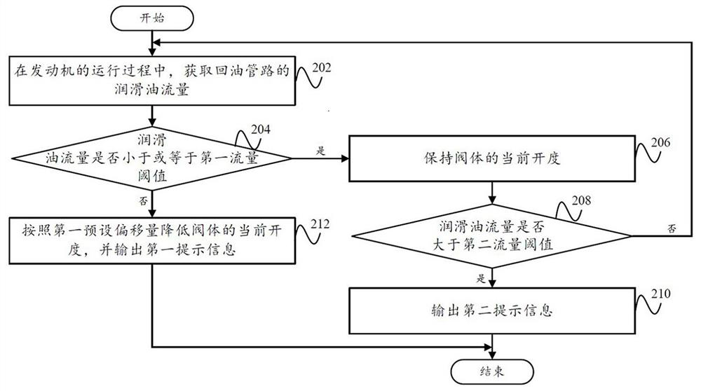
[0055] Such as figure 2 As shown, according to an embodiment of the present invention, a control method for an engine system is proposed, including:

[0056] Step 202, during the running of the engine, obtain the lubricating oil flow rate of the oil return pipeline;

[0057] Step 204, whether the lubricating oil flow is less than or equal to the first flow threshold, if so, go to step 206, if not, go to step 212;

[0058] Step 206, maintaining the current opening of the valve body;

[0059] Step 208, whether the lubricating oil flow is greater than the second flow threshold, if so, go to step 210, if not, go to step 202;

[0060] Step 210, outputting second prompt information;

[0061] Step 212, reducing the current opening of the valve body according to the first preset offset, and outputting first prompt information.

[0062] Wherein, the first traffic threshold is greater than the second traffic threshold.

[0063] In this embodiment, during the running of the engine,...

Embodiment 3

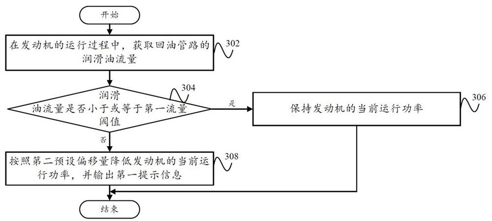
[0069] Such as image 3As shown, according to an embodiment of the present invention, a control method for an engine system is proposed, including:

[0070] Step 302, during the running of the engine, obtain the lubricating oil flow of the oil return line;

[0071] Step 304, whether the lubricating oil flow is less than or equal to the first flow threshold, if so, go to step 306, if not, go to step 308;

[0072] Step 306, maintaining the current operating power of the engine;

[0073] Step 308, reducing the current operating power of the engine according to the second preset offset, and outputting a first prompt message.

[0074] In this embodiment, during the running of the engine, the current operating power of the engine can also be adjusted according to the size relationship between the lubricating oil flow and the first flow threshold, thereby adjusting the lubricating oil flow from the engine into the supercharger .

[0075] Specifically, when the lubricating oil flo...


PUM


Abstract

The invention provides a control method, a control device and an engine system of an engine system, belonging to the technical field of engine system control. Wherein, the control method of the engine system includes: obtaining the lubricating oil flow of the oil return pipeline during the running of the engine; and controlling the valve body and / or the engine according to the lubricating oil flow. Therefore, according to the lubricating oil flow rate, it is judged whether the supercharger has a fault, and the valve body and / or the engine are adjusted when a fault occurs. Thereby reducing the amount of lubricating oil flow from the engine into the supercharger, effectively avoiding serious failures such as engine fire caused by lubricating oil participating in combustion, engine lack of lubricating oil and premature wear when the supercharger rotor or seal fails, and then increasing Protect the supercharger and engine in advance when the supercharger is working abnormally.

Description

technical field [0001] The present invention relates to the technical field of engine system control, in particular to an engine system control method, a control device and an engine system. Background technique [0002] At present, the protection methods for the exhaust gas turbocharger mainly include: judging whether the supercharger is faulty by checking whether the temperature of the coolant exceeds the limit value, and then controlling the supply of lubricating oil so that the lubrication of the supercharger always meets the lubrication requirements to ensure Supercharger operates safely. However, when the supercharger fails, the rotor system of the supercharger is damaged and the sealing system fails. At this time, the lubricating oil can still be cooled through the supercharger, resulting in the lag of the temperature change of the coolant, which cannot reflect the supercharger in time. Changes in the lubrication state lead to large fault detection errors, and even e...

Claims


Application Information

Patent Timeline
Patent Type & Authority Patents(China)
IPC IPC(8): F02B39/14
CPCF02B39/14
Inventor 周成尧丁树峰李昊
Owner HUNAN DEUTZ POWER CO LTD
Why Eureka
Try Eureka