Intelligent household water dispenser
A smart home, water dispenser technology, applied in home appliances, applications, kitchen appliances, etc., can solve the problems of unhealthy human body, repeated heating of water, poor practical effect, etc.
- Summary
- Abstract
- Description
- Claims
- Application Information
AI Technical Summary
Problems solved by technology
Method used
Image
Examples
Embodiment 1
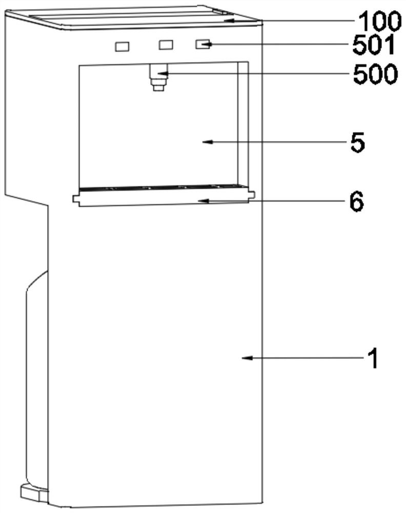
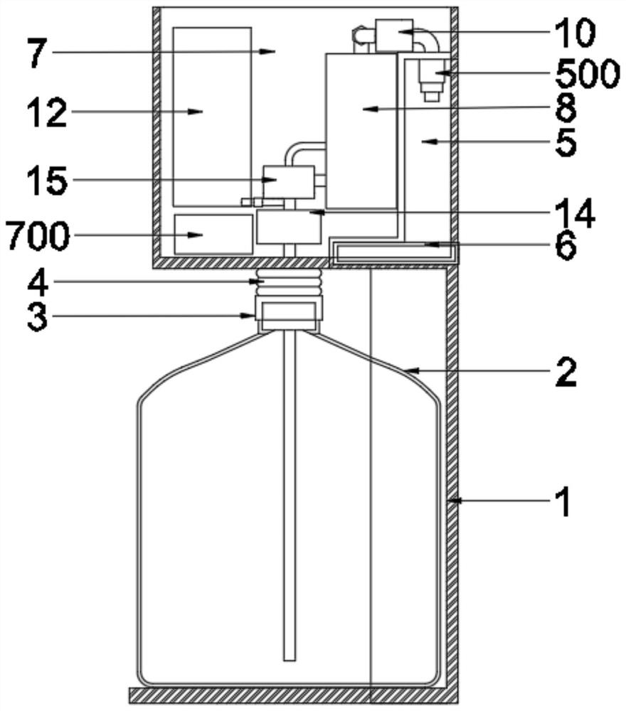
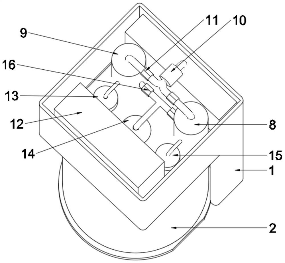
[0029] see Figure 1~6 , in an embodiment of the present invention, a smart home water dispenser includes a housing 1 and a bucket 2, the front end of the housing 1 is provided with a number of touch screen buttons 501, the front end of the housing 1 is provided with a water tank 5, the water tank 5 There is a water receiving box 6 inside, and the water receiving box 6 is slidably connected with the housing 1, and the inside of the housing 1 is provided with an installation chamber 7, which is located in the upper half of the housing 1, and the top of the housing 1 is provided with a top Cover 100, the upper end of the top cover 100 is provided with a square opening, the lower end of the top cover 100 is located in the installation chamber 7 and is provided with a storage box 102, the storage opening of the storage box 102 is aligned with the square opening, and the upper end of the top cover 100 A cover plate 101 is installed at the position corresponding to the storage box 1...
Embodiment 2
[0031] Please refer to Figure 7, the difference in connection with the basis of Embodiment 1 is that the hoses at the lower ends of the first water pump 10 and the third water pump 14 are connected by a connecting pipe 200, and the connecting pipe between the first water pump 10 and the hoses 200 is provided with a fifth solenoid valve 201 , and the fifth solenoid valve 201 is electrically connected to the control board 700 .
Embodiment 3
[0033] Please refer to Figure 8 , 9 , in conjunction with the basis of embodiment 1, the inside of the heat preservation box 12 is provided with a heat preservation pipe 120, and one end of the heat preservation pipe 120 is provided with a temperature sensor 121, and the temperature sensor 121 is electrically connected with the control board 700, and the heat preservation pipe 120 is a double-layer ceramic pipe. The double-layer ceramic tube can increase the heat preservation time and prevent the loss of temperature. One end of the heat preservation pipe 120 is connected with the pipeline between the second water pump 13 and the heat preservation box 12, and the other end is connected with the fourth water pump 15 and the heat preservation box 12. pipe connection between.
[0034] The working principle of the present invention is:
[0035] During the use of the present invention, open the first solenoid valve 11 between the third water pump 14, the first water pump 10 and t...
PUM
 Abstract
Description
Claims
Application Information
 - R&D
- Intellectual Property
- Life Sciences
- Materials
- Tech Scout
- Unparalleled Data Quality
- Higher Quality Content
- 60% Fewer Hallucinations
Browse by: Latest US Patents, China's latest patents, Technical Efficacy Thesaurus, Application Domain, Technology Topic, Popular Technical Reports.
© 2025 PatSnap. All rights reserved.Legal|Privacy policy|Modern Slavery Act Transparency Statement|Sitemap|About US| Contact US: help@patsnap.com


