Asymmetric steel plate hoisting equipment

A kind of hoisting equipment, asymmetric technology, applied in the direction of safety devices, transportation and packaging, load hanging components, etc., can solve problems such as falling, equipment damage, fixture damage, etc., to achieve good use effect, high safety, structure simple effect

Inactive Publication Date: 2021-08-27
杭州谦泰五金机械制造有限公司
0 Cites 2 Cited by

AI-Extracted Technical Summary

Problems solved by technology

[0002] In the process of steel plate processing, when the steel plate has been pre-processed, the center of gravity of the steel plate is often not at its original center position due to its irregular shape, and it is impossible to know the position of the center of gravity of the steel plate before it is hoisted, making the steel plate Swing around its own center ...

Method used

In summary, the beneficial effects of the present invention are: the present invention makes the center of gravity of the lifted asymmetrical irregular steel plate 53 be located on the central axis of the suspension tube 1 by adjusting the expansion and contraction of each suspension rope B34 in turn and makes The steel plate 53 is in a horizontal state, which prevents the asymmetrical steel plate 53 from swingi...

Abstract

The invention belongs to the field of steel plate hoisting, and particularly relates to asymmetric steel plate hoisting equipment. The asymmetric steel plate hoisting equipment comprises a hoisting cylinder, a plurality of winding wheels, an electric drive module, hoisting ropes B and a fixture mechanism, the hoisting cylinder is mounted on a hoisting rope A of a crane, and the multiple winding wheels which are driven by the electric drive module are mounted in the hoisting cylinder and are uniformly distributed in the circumferential direction, and the central axis of each winding wheel is perpendicular to the central axis of the hoisting cylinder. According to the asymmetric steel plate hoisting equipment, the gravity center of a hoisted asymmetric irregular steel plate is located on the central axis of the hoisting cylinder and the steel plate is in a horizontal state by sequentially adjusting the expansion and contraction amount of each hoisting rope B, the situation that part of clamp mechanisms are damaged due to the fact that the asymmetric steel plate swings around the gravity center due to center-of-gravity shift is avoided, and high safety is achieved; and meanwhile, the asymmetric steel plate in the hoisting process is in a horizontal state under the action of the device, so that the situation that the ground is seriously damaged due to inclination of the steel plate after the steel plate falls off is avoided.

Application Domain

Safety gear

Technology Topic

Steel platesElectric drive +2

Image

  • Asymmetric steel plate hoisting equipment
  • Asymmetric steel plate hoisting equipment
  • Asymmetric steel plate hoisting equipment

Examples

  • Experimental program(1)

Example Embodiment

[0029] The accompanying drawings are all schematic diagrams of the implementation of the present invention, so as to understand the principle of structural operation. The specific product structure and proportional size can be determined according to the use environment and conventional technology.
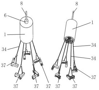
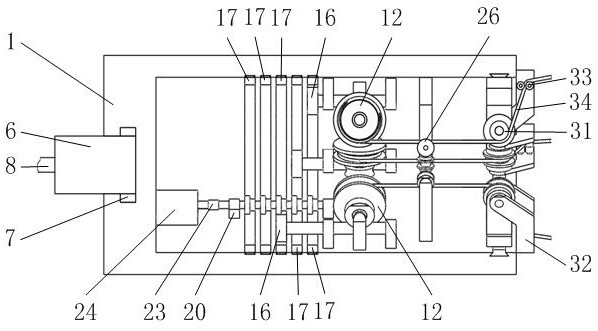
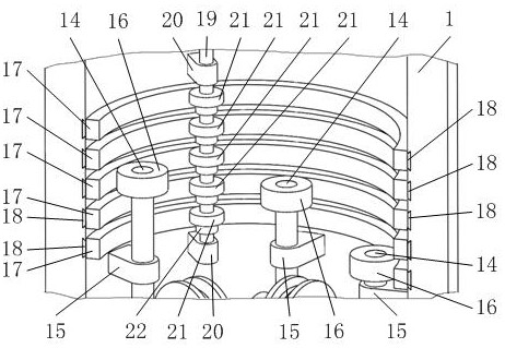
[0030] like figure 1 , 2 As shown, it includes a suspension tube 1, a winding wheel 12, an electric drive module 24, a sling B34, and a fixture mechanism 37, wherein as figure 1 , 2 , 5, the suspension tube 1 is installed on the crane rope A8, and the suspension tube 1 is equipped with a plurality of winding wheels 12 driven by the electric drive module 24 that are uniformly distributed in the circumferential direction and whose central axis is perpendicular to the central axis of the suspension tube 1; figure 1 , 2 , 6, each winding wheel 12 is wound with a suspension rope B34, and each suspension rope B34 end is equipped with a fixture mechanism 37 that cooperates with the steel plate 53; figure 2 , 4 , 8, the suspension tube 1 is equipped with a structure that prevents the suspension rope B34 from rubbing against the inner wall of the suspension tube 1 and is convenient for the suspension rope B34 to swing around the central axis of the suspension tube 1 .
[0031] like Figure 9 , 10 As shown, the above-mentioned fixture mechanism 37 includes a clamping hand A38, a clamping hand B43, a pressing plate 46, a bolt 47, an outer cover 48, a round pin A50, an inner rod 51, and a round pin B52, wherein as Image 6 As shown, the middle part of the upper end face of the gripper A38 and the gripper B43 is connected by a branch rope 36, and the branch rope 36 passes through the slip ring 35 at the end of the corresponding suspension rope B34; Figure 11 As shown, the grip A38 and the grip B43 all have a draw-in groove 39 that cooperates with the edge of the steel plate 53; Figure 9 , 10As shown, in the draw-in slot 39 of the hand A38 and the hand B43, there is a pressing plate 46 for clamping the steel plate 53; Cooperate, the pressing plate 46 in the clamping hand B43 rotates and cooperates with the bolt 47 screwed in the threaded hole 40 on the clamping hand B43; Figure 10 , 11 As shown, the outer bottom of the gripper A38 is provided with a lock slot A41 communicating with the side wall where the slot 39 is located. A round pin A50 whose central axis is perpendicular to the surface of the steel plate 53 is installed in the lock slot A41. The round pin A50 is rotated and axially There is an overcoat 48 in sliding fit; the outer bottom of the clamping hand B43 is provided with a lock groove B45 communicating with the end wall where the draw groove 39 is located, and a round pin B52 whose central axis is perpendicular to the plate surface of the steel plate 53 is installed in the lock groove B45, and on the round pin B52 Rotate and axially slide with an inner rod 51; the card slot 39A and the card slot 39B communicate when the card hand A38 and the card hand B43 are vertically docked; as Figure 10 , 12 13, the inner rod 51 telescopically slides in the overcoat 48; some threaded holes 40 on the overcoat 48 are internally screwed with bolts 47 that cooperate with the inner rod 51; Figure 10 , 11 As shown, the handle A38 has a structure for tightly pressing and fixing the jacket 48 to the bottom of the handle A38, and the handle B43 has a structure for tightly pressing and fixing the inner rod 51 to the bottom of the handle B43.
[0032] like Figure 10 , 11 As shown, the locking groove A41 at the outer bottom of the above-mentioned hand A38 is equipped with an L-shaped support E42 surrounding the outer cover 48, and the upper thread of the support E42 is fitted with a bolt 47 that cooperates with the outer bottom 48; the locking groove B45 at the outer bottom of the hand B43 is An L-shaped support E42 surrounding the inner rod 51 is installed at the place, and the bolt 47 matched with the inner rod 51 is threaded on the support E42.
[0033] like figure 2 , 7 As shown, the circular groove 5 at one end of the above-mentioned hanging tube 1 is rotated and fitted with a rotating column 6 connected with the suspension rope A8; ;like Figure 4 , 8 As shown, on the inner wall of the lower end of the suspension tube 1, sliding around the central axis of the suspension tube 1, there are some sliders 27 corresponding to the winding wheels 12; each slider 27 is equipped with a U seat B29, and each U seat B29 has a The support wheel 31 supporting the suspension rope B34 on the corresponding winding wheel 12 is installed; the shaft B30 where the support wheel 31 is located is rotated and fitted with two bearings C32, and two bearings that cooperate with the corresponding suspension rope B34 are installed between the two bearings C32. The guide wheel 33 ; the suspension rope B34 wound on the winding wheel 12 goes downwards around the corresponding support wheel 31 and the two guide wheels 33 in turn.
[0034] like Figure 5 As shown, the winding wheel 12 is installed on the shaft A10 where it is located through the shaft sleeve 11, and the shaft A10 is installed between the two supports A9 on the inner wall of the suspension tube 1; the worm gear 13 coaxial with the winding wheel 12 is installed on the shaft sleeve 11 ;like image 3 , 4 , 5, the worm 14 meshed with the turbine is installed on the inner wall of the hanging tube 1 through two bearings B15 that are rotatably matched with it; each worm 14 is equipped with a gear A16; The ring gear 17 distributed at intervals meshes with the gear A16 on the worm 14 in one-to-one correspondence; the shaft C19 is installed on the inner wall of the hanging tube 1 through two supports D20 that rotate with it; several gears B21 that mesh with the ring gear 17 in one-to-one correspondence They are respectively installed on the shaft C19 through the electronically controlled clutch 22; the shaft C19 is connected to the output shaft of the electric drive module 24 through the coupling 23. All are connected to the output shaft of the electric drive module 24 that drives the corresponding winding wheel 12 to rotate through a coupling 23 .
[0035] like figure 2 As shown, the part of the suspension rope B34 in contact with the supporting wheel 31 is close to the central axis of the suspension tube 1, so as to ensure that the lower end of the suspension rope B34 will not produce a large arc displacement when swinging around the central axis of the suspension cylinder 1, so that the suspension rope B34 is opposite to the central axis of the suspension tube 1. The active force of the winding wheel 12 is always substantially perpendicular to the central axis of the winding wheel 12 .
[0036] like Figure 4 , 7 , 8, the above-mentioned slider 27 is equipped with an arc-shaped trapezoidal guide block 28, and the arc-shaped trapezoidal guide block 28 slides in the annular trapezoidal guide groove A3 on the inner wall of the lower end of the hanging tube 1 around the central axis of the hanging tube 1. The cooperation of the trapezoidal guide groove A3 and the trapezoidal guide block 28 plays a positioning and guiding role on the sliding of the slider 27 on the inner wall of the hanging tube 1 around the central axis of the hanging tube 1 . The inner wall of the suspension tube 1 is equipped with a number of positioning wheels 26 that are evenly distributed in the circumferential direction and that are matched one-to-one with the hanging rope B34 on the winding wheel 12 through the U seat A25; the positioning wheels 26 are located between the corresponding winding wheel 12 and the corresponding support wheel 31 The positioning wheel 26 presses the corresponding suspension rope B34 on the winding wheel 12; each ring gear 17 is equipped with a trapezoidal guide ring 18, and the trapezoidal guide ring 18 rotates in the trapezoidal guide groove B4 on the inner wall of the suspension tube 1. The cooperation of the trapezoidal guide ring 18 and the trapezoidal guide groove B4 plays a positioning and guiding role for the rotation of the ring gear 17 on the inner wall of the suspension tube 1 .
[0037] The electric drive module 24 in the present invention adopts the prior art, and it is mainly made up of motor, speed reducer and control unit.
[0038] The electronically controlled clutch 22 among the present invention adopts prior art.
[0039] The working process of the present invention: in the initial state, all the bolts 47 threaded on the outer sleeve 48 of the fixture mechanism 37 are tightened and the corresponding inner rods 51 are tightened, and the relative position between the outer sleeve 48 and the inner rod 51 is locked. If the grip A38 and the grip B43 are in the initial state parallel to each other or facing each other, then the bolt 47 on the grip A38 that is threaded with the support E42 is tightened and the outer sleeve 48 is tightly pressed against the grip At the outer bottom of A38, the bolt 47 threaded with the support E42 on the handle B43 is tightened and the inner rod 51 is tightly pressed against the outer bottom of the handle B43. If the card hand A38 and the card hand B43 are in a mutually perpendicular state in the initial state, then the bolt 47 on the card hand A38 that is threaded with the support E42 is tightened and the outer cover 48 is tightly pressed against the card at the bottom of the outer side of the card hand A38. In the groove 39A, the bolt 47 on the handle B43 threadedly engaged with the support E42 is tightened and the inner rod 51 is tightly pressed against the groove 39B at the outer bottom of the handle B43.
[0040] In the initial state, the lengths of the respective hanging ropes B34 are equal.
[0041] like Figure 14 As shown, when using the present invention to hoist the semi-processed asymmetric steel plate 53, first adjust the fixture mechanism 37 according to the shape of the hoisted asymmetric steel plate 53, if several hoisting force points on the edge of the steel plate 53 are at right angles Stress point 54, then the clamping hand A38 and clamping hand B43 in the clamp mechanism 37 of the right-angled force point 54 are adjusted to a mutually perpendicular right-angle shape. If some force points on the edge of the steel plate 53 are narrow and long force points 56 respectively, then the grip A38 and the grip B43 in the clamp mechanism 37 of the narrow and long force points 56 are adjusted to be parallel to each other and to the narrow and long force points 56 Both sides form a hooked state. If some force points on the edge of the steel plate 53 are respectively straight edge force points 55, then the clamping hand A38 and the clamping hand B43 in the fixture mechanism 37 hooking the straight edge force point 55 are docked and extended, increasing the clamp mechanism 37 pairs The hook length of the straight edge force point 55 makes the hook more stable.
[0042] The operation process for adjusting the clamping hand A38 and the clamping hand B43 of the fixture mechanism 37 to be perpendicular to each other is as follows:
[0043] Regardless of whether the gripper A38 and the gripper B43 are in the mutual butt extension state or in the state of being parallel to each other, loosen the bolt 47 on the gripper A38 that is threaded with the corresponding support E42 and the bolt 47 on the gripper B43 that is threaded with the corresponding support E42. Bolt 47, release bolt 47 and cover 48 and inner rod 51 are pressed tightly to the bottom of clamping hand A38 and clamping hand B43 respectively, so that the outer cover 48 can swing around the round pin A50 relative to the clamping hand A38, and the inner rod 51 can go around The round pin B52 swings relative to the gripper B43. Then unscrew all the bolts 47 threaded on the outer sleeve 48 and remove the fixation to the corresponding inner rod 51 , so that the inner rod 51 can slide freely relative to the outer sleeve 48 .
[0044] After the inner rod 51 and the overcoat 48 are relatively elongated by a certain distance, the grip A38 is swung around the round pin A50 relative to the overcoat 48 to a state perpendicular to the overcoat 48, and the grip B43 is swung around the round pin B52 relative to the inner rod 51 to a position perpendicular to the overcoat 48. A state where the inner rods 51 are parallel. When the clamping hand A38 is perpendicular to the overcoat 48, the overcoat 48 is just opposite to the draw-in groove 39A at the outer bottom of the clamping hand A38. When the locking hand B43 is parallel to the inner rod 51 , the inner rod 51 is just opposite to the locking groove 39B at the outer bottom of the locking hand B43 .
[0045] The inner rod 51 is retracted in the overcoat 48 until one end of the clamping hand B43 is in contact with the side wall of the slot of the clamping hand A38, then all the bolts 47 threaded on the overcoat 48 are tightened in turn and the inner rod 51 and the overcoat 48 are tightened. The relative position between them is locked and fixed again, and then the bolt 47 on the hand A38 that is threaded with the corresponding support E42 and the bolt 47 on the hand B43 that is threaded with the corresponding support E42 are tightened, so that the overcoat 48 is embedded The clamping groove 39A is tightly opposed to the clamping hand A38, and the inner rod 51 is inserted into the clamping groove 39B to tightly contact the clamping hand B43, thereby completing the adjustment of the clamping hand A38 and the clamping hand B43 in the clamp mechanism 37 at right angles to the vertical state.
[0046] The operation process for adjusting the clamping hand A38 and the clamping hand B43 of the fixture mechanism 37 to be parallel to each other is as follows:
[0047] Sequentially unscrew the bolt 47 on the hand A38 that is threaded with the corresponding support E42 and the bolt 47 on the hand B43 that is threaded with the corresponding support E42, release the bolt 47 and move the outer cover 48 and the inner rod 51 to the hand A38 and the card respectively. The tight pressing of the bottom of the hand B43 makes the outer cover 48 and the inner rod 51 vertically break away from the draw-in groove 39A and the draw-in groove 39B respectively, so that the outer cover 48 can swing around the circular pin A50 relative to the clamping hand A38, and the inner rod 51 can go around the circular pin A50. The pin B52 swings relative to the grip B43. Then unscrew all the bolts 47 threaded on the outer sleeve 48 and remove the fixation to the corresponding inner rod 51 , so that the inner rod 51 can slide freely relative to the outer sleeve 48 .
[0048] After the relative position of the inner rod 51 and the outer cover 48 is fixed and released, the inner rod 51 and the outer cover 48 are relatively extended by a certain distance, so that the locking hand A38 swings around the round pin A50 relative to the outer cover 48 to a state perpendicular to the outer cover 48. B43 swings around the round pin B52 relative to the inner rod 51 to a state perpendicular to the inner rod 51 . When the clamping hand A38 is perpendicular to the overcoat 48, the overcoat 48 is just opposite to the draw-in groove 39A at the outer bottom of the clamping hand A38. When the gripping hand B43 is perpendicular to the inner rod 51, the inner rod 51 is just perpendicular to the locking groove 39B at the outer bottom of the gripping hand B43. Then, adjust the relative length of the inner rod 51 and the overcoat 48 according to the width of the narrow and long focus point 56 on the steel plate 53, until the clamping hand B43 and the clamping hand A38 are just stuck on both sides of the narrow and long focus point 56, the overcoat 48 is placed on the All the bolts 47 that are threaded are tightened and the relative position between the inner rod 51 and the outer cover 48 is locked and fixed again. Place a spacer with the same thickness as the wall thickness of the jacket 48 between the hand B43 and the bolt 47 on the hand A38 that is threaded with the corresponding support E42 and the bolt 47 on the hand B43 that is threaded with the corresponding support E42. Tight, so that the outer cover 48 is tightly pressed against the clamping hand A38 through the cushion block, and the inner rod 51 is tightly pressed against the outer bottom of the clamping hand B43 through the cushion block. The slot 39 is exactly opposite to the slot 39 of the clamping hand B43 , so that the adjustment of the clamping hand A38 and the clamping hand B43 in the clamp mechanism 37 in a parallel relative state is completed.
[0049] The operation process for adjusting the clamping hand A38 and the clamping hand B43 of the fixture mechanism 37 to be mutually docked and extended is as follows:
[0050]Sequentially unscrew the bolt 47 on the hand A38 that is threaded with the corresponding support E42 and the bolt 47 on the hand B43 that is threaded with the corresponding support E42, release the bolt 47 and move the outer cover 48 and the inner rod 51 to the hand A38 and the card respectively. The tight pressing of the bottom of the hand B43 makes the outer cover 48 and the inner rod 51 vertically break away from the draw-in groove 39A and the draw-in groove 39B respectively, so that the outer cover 48 can swing around the circular pin A50 relative to the clamping hand A38, and the inner rod 51 can go around the circular pin A50. The pin B52 swings relative to the grip B43. Then unscrew all the bolts 47 threaded on the outer sleeve 48 and remove the fixation to the corresponding inner rod 51 , so that the inner rod 51 can slide freely relative to the outer sleeve 48 .
[0051] After the relative position of the inner rod 51 and the outer cover 48 is fixed and released, the inner rod 51 and the outer cover 48 are relatively extended by a certain distance, so that the locking hand A38 swings around the round pin A50 relative to the outer cover 48 to a state parallel to the outer cover 48. B43 swings around the round pin B52 relative to the inner rod 51 to a state parallel to the inner rod 51 . When the card hand A38 is parallel to the overcoat 48, the overcoat 48 is just perpendicular to the draw-in groove 39A at the outer bottom of the card hand A38. When the locking hand B43 is parallel to the inner rod 51 , the inner rod 51 is just opposite to the locking groove 39B at the outer bottom of the locking hand B43 . Then, according to the relative length of the adjustment inner rod 51 and the outer cover 48, when the side ends of the gripper B43 and the gripper A38 are completely docked, all the bolts 47 that are threaded on the outer jacket 48 are tightened in turn and the inner rod 51 and the outer jacket 48 are tightened. The relative position between them is locked and fixed again, and then, place a block with the same thickness as the sum of the depth of the slot 39B and the wall thickness of the jacket 48 in the slot 39B, and then thread the hook A38 with the corresponding support E42 in turn. The bolt 47 of the bolt 47 and the bolt 47 threaded with the corresponding support E42 on the hand B43 are tightened, so that the outer cover 48 and the hand A38 are tightly pressed against each other, and the inner rod 51 is tightly pressed against the hand B43 through the spacer, so that the hand A38 The draw-in slot 39 and the draw-in slot 39 of the clamping hand B43 are just completely docked, thereby completing the adjustment of the clamping hand A38 and the clamping hand B43 in the butt joint extension state in the clamp mechanism 37 .
[0052] After adjusting the relative positions of the clamping hand A38 and the clamping hand B43 in each clamping mechanism 37, the nested hooks of the adjusted clamping mechanism 37 are respectively hung on the corresponding right-angle force point 54 or straight edge on the steel plate 53. On the focus point 55 or the narrow and long focus point 56, then turn the bolt 47 on the clamping hand A38 and the clamping hand B43 in each fixture mechanism 37 to rotate with the pressing plate 46, and the bolt 47 drives the pressing plate 46 to the plate surface of the steel plate 53 Carry out tight pressing, thus complete the hooking and fixing of the clamp mechanism 37 to the corresponding force point on the steel plate 53 .
[0053] After the fixture mechanism 37 hooks and fixes the steel plate 53, the crane lifts the steel plate 53 upwards through the present invention. During the lifting process of the steel plate 53, since the center of gravity of the asymmetrical steel plate 53 is not at its geometric center position, the asymmetrical steel plate 53 will be distorted. The part where the center of gravity is located will swing downwards around the point where the two connecting lines on the steel plate 53 are offset from the center of gravity of the steel plate 53 and is not horizontal until the part of the fixture mechanism 37 on the part where the center of gravity of the steel plate 53 is fully stressed . During this process, the clip mechanism 37 on the upturned part of the steel plate 53 is not stressed. During the hoisting process, each fixture mechanism 37 will drive the corresponding slider 27 around the inner wall of the hanging tube 1 through the corresponding support rope 36, the hanging rope B34, the two guide wheels 33, the two bearings C32 and the corresponding U seat B29. 1 The central axis produces adaptive small-scale sliding.
[0054] When the tilted state of the steel plate 53 is stable and fixed, adjust the steel plate 53 from the tilted state to the horizontal state by visual inspection, and the adjustment process is as follows:
[0055] The electronic control clutch 22 and the electric drive module 24 corresponding to the part of the fixture mechanism 37 on the lower part of the steel plate 53 are sequentially controlled by the control system to work, and the electric drive module 24 drives the corresponding gear B21 through the shaft C19 and the electric control clutch 22 in the working state. Rotate, the rotating gear B21 drives the corresponding worm 14 to rotate through the corresponding ring gear 17 and gear A16, and the worm 14 drives the corresponding winding wheel 12 to wind the corresponding hanging rope B34 through the corresponding worm gear 13 and bushing 11, and the wrapped hanging rope B34 and The included angle between the steel plates 53 gradually increases, and the suspension rope B34 passes through the corresponding two guide wheels 33 to drive the corresponding two bearings C32 to swing upward around the corresponding axes B30 until the steel plates 53 are in a horizontal state.
[0056] During the swinging process of the steel plate 53 to the horizontal state, if the suspension rope B34 which was in the slack state in the initial lifting process is gradually stretched straight and hinders the upward swing of the part where the center of gravity of the steel plate 53 is located to the horizontal state, then at this time, the control winding hoisting The electronically controlled clutch 22 corresponding to the rope B34 stops working, and then controls the electronically controlled clutch 22 corresponding to the lifting rope B34 that limits the upper swing of the steel plate 53 center of gravity to work, and controls the electric drive module 24 to run in reverse at the same time. 24 drives the steel plate 53 hem parts by a series of transmissions and is in stretched straight state and forms the corresponding winding wheel 12 rotation of the suspension rope B34 that steel plate 53 swings limit, and winding wheel 12 broadcasts suspension rope B34. After the hanging rope B34 is released long enough, control the electronically controlled clutch 22 corresponding to the released hanging rope B34 to stop working, and control the electric drive module 24 to stop running.
[0057] Then, the electric control clutch 22 and the electric drive module 24 corresponding to the clamp mechanism 37 on the position of the center of gravity of the steel plate 53 are controlled by the control system to work again, and the electric drive module 24 drives the corresponding winding wheel 12 through a series of transmissions such as the electric control clutch 22 Continue to wind the corresponding suspension rope B34, and the wound suspension rope B34 continues to lift the center of gravity of the steel plate 53 to the horizontal position until the steel plate 53 is in the horizontal position and stops the operation of the electronically controlled clutch 22 and the electric drive module 24.
[0058] After the steel plate 53 is in the horizontal state, part of the suspension ropes B34 will be in a relaxed state, and the control system will sequentially control the operation of the electronically controlled clutch 22 and the electric drive module 24 corresponding to each of the loose suspension ropes B34, and the electric drive module 24 will pass A series of transmissions such as the electronically controlled clutch 22 in the working state drive the corresponding winding wheel 12 to wind the corresponding hanging rope B34, and stop the electric drive module 24 and the electronically controlled clutch when all the hanging ropes B34 in the relaxed state are in a stretched state under force. 22 runs.
[0059] After the electric drive module 24 and the electric control clutch 22 stop working, the worm 14 and the worm wheel 13 corresponding to each fixture mechanism 37 have a self-locking function, so the force of the hanging rope B34 will not drive the winding wheel 12 to reverse , so as to ensure that the hoisting state of the steel plate 53 by the suspension rope B34 is unchanged, and then ensure that the adjusted horizontal state of the steel plate 53 will not change in the subsequent continuous hoisting process, so that the force points of each part of the asymmetrical steel plate 53 are hooked. The hanging clip mechanism 37 will not be damaged due to abnormal force. In addition, the steel plate 53 which is adjusted to be horizontal will not cause serious damage to the ground if dropped.
[0060] In summary, the beneficial effects of the present invention are: the present invention makes the center of gravity of the lifted asymmetrical irregular steel plate 53 on the central axis of the hanging tube 1 and makes the steel plate 53 in the In the horizontal state, the asymmetrical steel plate 53 is prevented from swinging around the center of gravity due to the offset of the center of gravity, which will cause damage to part of the fixture mechanism 37, which has higher safety. At the same time, the asymmetrical steel plate 53 in the hoisting process is in a horizontal state under the action of the present invention, which ensures that the steel plate 53 will not cause serious damage to the ground due to its inclination after falling.

PUM

no PUM

Description & Claims & Application Information

We can also present the details of the Description, Claims and Application information to help users get a comprehensive understanding of the technical details of the patent, such as background art, summary of invention, brief description of drawings, description of embodiments, and other original content. On the other hand, users can also determine the specific scope of protection of the technology through the list of claims; as well as understand the changes in the life cycle of the technology with the presentation of the patent timeline. Login to view more.

Similar technology patents

Malicious website prompt method and router

ActiveCN104125209Aimprove security
Owner:TENCENT TECH (SHENZHEN) CO LTD +1

Credible virtual machine platform

InactiveCN101957900AImprove stability and attack resistanceimprove security
Owner:706 INST SECOND RES INST OF CHINAAEROSPACE SCI & IND

Intelligent door lock identity authentication method and system, readable storage medium and mobile terminal

ActiveCN109712278APrevent Identity Leakageimprove security
Owner:深圳市小石安防科技有限公司

Classification and recommendation of technical efficacy words

  • Simple structure
  • improve security
Why Eureka
Try Eureka