
Winding machine for self-adhesive coil

A technology of winding machine and self-adhesive wire, which is applied in the direction of coil manufacturing, etc., can solve the problems of poor heating effect of self-adhesive coil, high labor intensity of staff, low production efficiency of self-adhesive coil, etc., and achieve good rotation effect and good cycle to the effect of heating

Inactive Publication Date: 2021-08-31
李夏君
View PDF0 Cites 0 Cited by
  • Summary
  • Abstract
  • Description
  • Claims
  • Application Information

AI Technical Summary

Problems solved by technology

[0002] At present, in the production process of self-adhesive coils, it is first necessary to wind the hot-air self-adhesive wire into a self-adhesive coil through a winding machine. The self-adhesive coil is removed from the winding machine, and then the self-adhesive coil after winding needs to be heated manually by hand-held heat gun. After the self-adhesive coil is heated, the two adjacent hot air self-adhesive wires can Mutual bonding to avoid loosening of the self-adhesive coils; however, in the production process of the above-mentioned self-adhesive coils, the heating of the self-adhesive coils needs to be achieved by hand-held heat guns, so that not only the self-adhesive coils are heated The disadvantage of poor effect, but also the disadvantages of low production efficiency of self-adhesive coils and high labor intensity of staff

Method used


Image

  • Winding machine for self-adhesive coil
  • Winding machine for self-adhesive coil
  • Winding machine for self-adhesive coil

Examples


Embodiment Construction

[0020] A number of embodiments of the present invention will be disclosed in the following figures. For the sake of clarity, many practical details will be described together in the following description. It should be understood, however, that these practical details should not be used to limit the invention. That is, in some embodiments of the invention, these practical details are not necessary. In addition, for the sake of simplifying the drawings, some well-known and commonly used structures and components will be shown in a simple schematic manner in the drawings.

[0021] In addition, in the present invention, descriptions such as "first", "second" and so on are used for description purposes only, and do not refer to the meaning of order or sequence, nor are they used to limit the present invention, but are only for the purpose of distinguishing the following The components or operations described by the same technical terms are only used, but should not be understood a...


PUM


Abstract

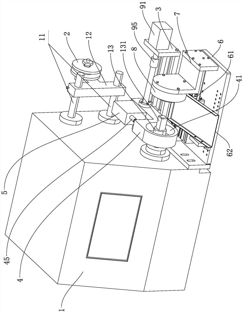
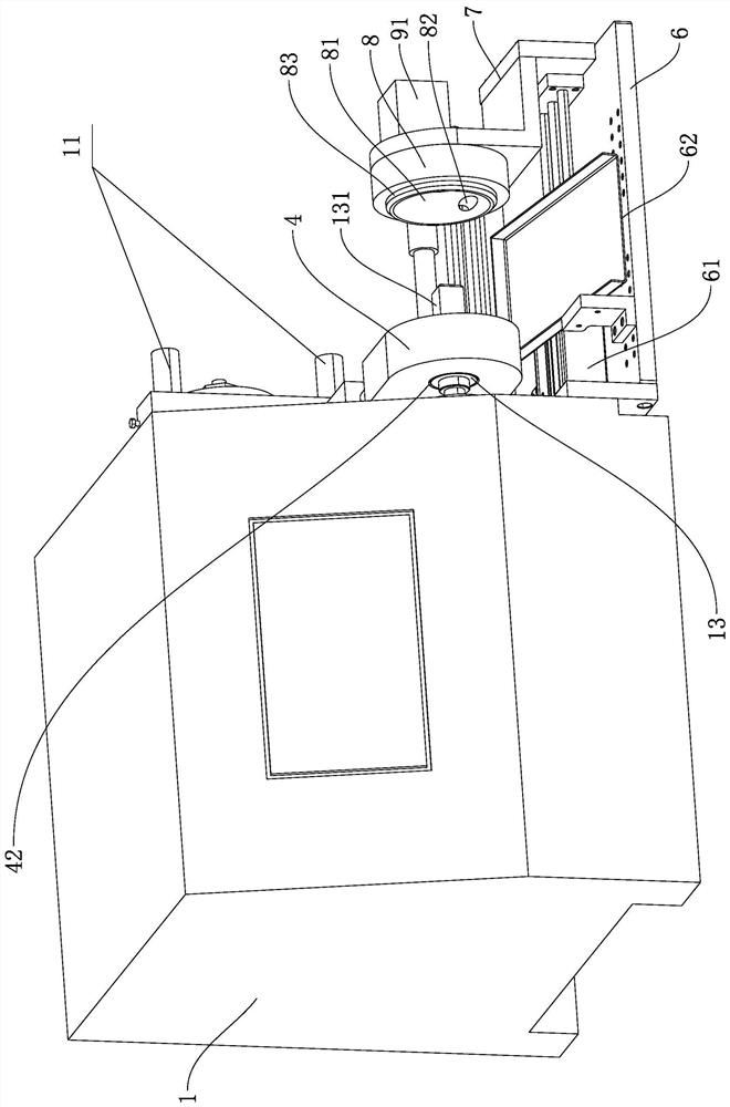
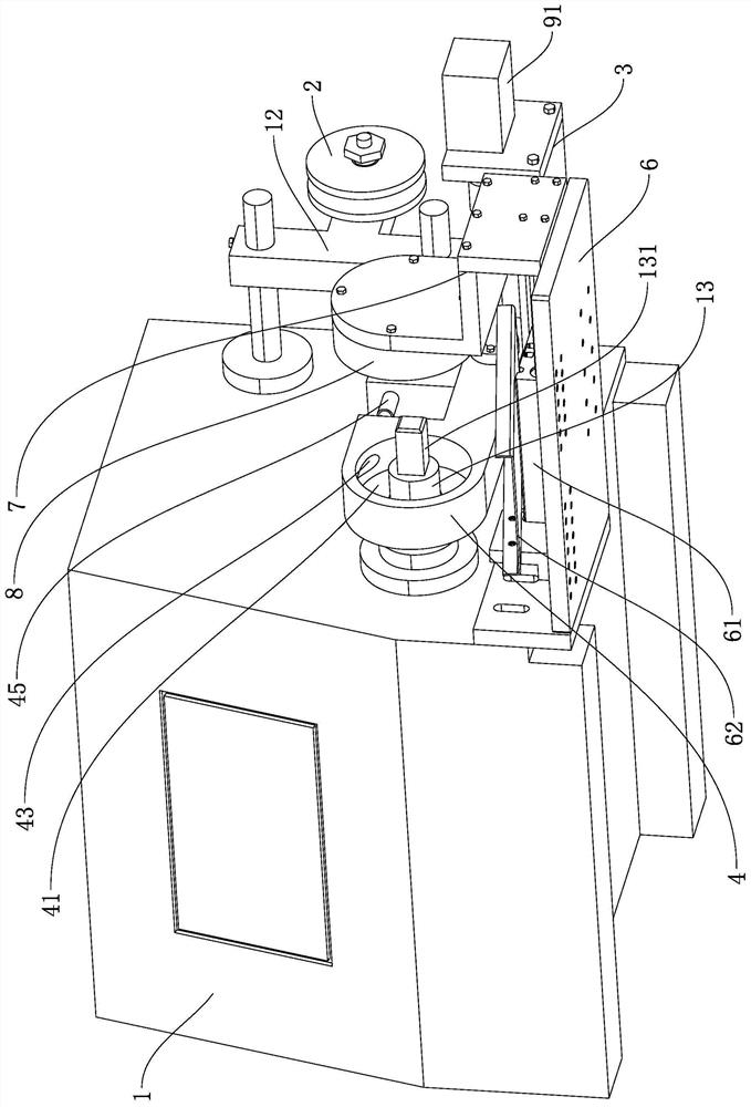
A winding machine for a self-adhesive coil, disclosed in the invention, comprises a winding machine body, a first support is fixed to the rear portion of the right side of the winding machine body, a sliding block is connected to the first support in a sliding mode, and a first driving mechanism is arranged on the first support; a first heating cavity with a right opening is formed in the front portion of the sliding block, a through hole communicated with the first heating cavity is formed in the left side of the front portion of the sliding block, a hot air gun is fixed to the sliding block, and the first heating cavity is communicated with a hot air outlet of the hot air gun; and a second support is fixed to the front portion of the right side of the winding machine body, a second driving mechanism is installed on the second support, a third support is fixed to the driving end of the second driving mechanism, an end cover is fixed to the side, facing the sliding block, of the third support, a second heating cavity with an opening in the left side is formed in the end cover, and an air outlet communicated with the second heating cavity is formed in the end cover. The winding machine can improve the heating effect on the self-adhesive coil, can improve the production efficiency of the self-adhesive coil, and reduces the labor intensity of workers.

Description

technical field [0001] The invention relates to the technical field of winding machines, in particular to a winding machine for self-adhesive coils. Background technique [0002] At present, in the production process of self-adhesive coils, it is first necessary to wind the hot-air self-adhesive wire into a self-adhesive coil through a winding machine. The self-adhesive coil is removed from the winding machine, and then the self-adhesive coil after winding needs to be heated manually by hand-held heat gun. After the self-adhesive coil is heated, the two adjacent hot air self-adhesive wires can Mutual bonding to avoid loosening of the self-adhesive coils; however, in the production process of the above-mentioned self-adhesive coils, the heating of the self-adhesive coils needs to be achieved by hand-held heat guns, so that not only the self-adhesive coils are heated It has the disadvantages of poor effect, and also has the disadvantages of low production efficiency of self-a...

Claims


Application Information

Patent Timeline
IPC IPC(8): H01F41/04H01F41/06
CPCH01F41/04H01F41/06
Inventor 李夏君
Owner 李夏君
Learn More