Winding machine with hot air self-adhesion wire tensioning structure

A technology of winding machine and self-adhesive wire, which is applied in the direction of electrical components, inductance/transformer/magnet manufacturing, circuits, etc., which can solve the problem of affecting the performance of self-adhesive coil products, not having a hot-air self-adhesive wire tensioning structure, and inconsistent tightness And other issues

Inactive Publication Date: 2021-09-07
李夏君
View PDF0 Cites 2 Cited by
  • Summary
  • Abstract
  • Description
  • Claims
  • Application Information

AI Technical Summary

Problems solved by technology

[0002] In the production process of self-adhesive coils, it is necessary to use a winding machine to wind self-adhesive coils, that is, after the hot air self-adhesive wire sent by the pay-off wheel inside the winding machine is wound by the winding shaft inside the winding machine, it can be A self-adhesive coil is formed on the winding shaft. In addition, after the winding of the self-adhesive coil is completed, the self-adhesive coil needs to be removed from the winding shaft manually, and then it is necessary to manually hold a heat gun to realize the alignment after the winding is completed. The heating of the self-adhesive coil, after the sel

Method used


Image

  • Winding machine with hot air self-adhesion wire tensioning structure
  • Winding machine with hot air self-adhesion wire tensioning structure
  • Winding machine with hot air self-adhesion wire tensioning structure

Examples


Embodiment Construction

[0023] A number of embodiments of the present invention will be disclosed in the following figures. For the sake of clarity, many practical details will be described together in the following description. It should be understood, however, that these practical details should not be used to limit the invention. That is, in some embodiments of the invention, these practical details are not necessary. In addition, for the sake of simplifying the drawings, some well-known and commonly used structures and components will be shown in a simple schematic manner in the drawings.

[0024] In addition, in the present invention, descriptions such as "first", "second" and so on are used for description purposes only, and do not refer to the meaning of order or sequence, nor are they used to limit the present invention, but are only for the purpose of distinguishing the following The components or operations described by the same technical terms are only used, but should not be understood as ...


PUM


Abstract

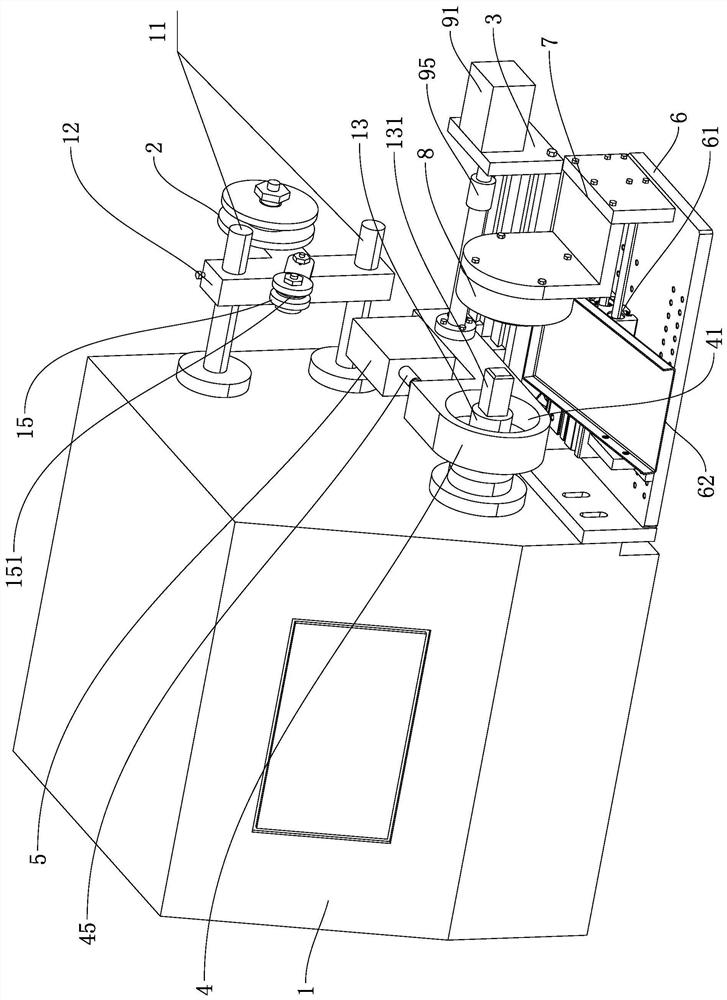
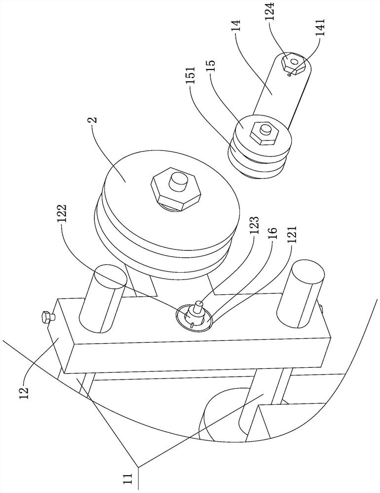
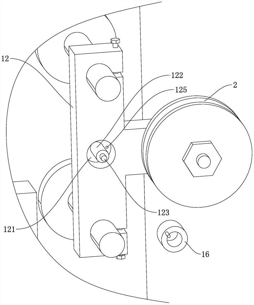
The invention discloses a winding machine with a hot air self-adhesion wire tensioning structure, and the winding machine comprises a winding machine body, a tier pole group is arranged at the rear part of the right side of the winding machine body, a pay-off rack is fixed on the tier pole group, a pay-off wheel is rotationally connected to the pay-off rack, a hot air self-adhesion wire is wound on the pay-off wheel, a winding shaft is arranged at the front part of the right side of the winding machine body, a winding part is arranged at the right end of the winding shaft, a rotating arm is rotationally connected to the pay-off rack, a tensioning wheel is rotationally connected to the end, away from the pay-off rack, of the rotating arm, and an annular groove used for clamping a hot air supply self-adhesion wire is formed in the peripheral wall of the tensioning wheel; a blind hole is formed in the side, facing the rotating arm, of the pay-off rack, a torsional spring sleeving the supporting shaft is arranged in the blind hole, and the torsional spring is used for driving the end, away from the pay-off rack, of the rotating arm to rotate upwards. According to the invention, the phenomenon that each strand of hot air self-adhesion wire in the self-adhesion coil wound on the winding shaft is inconsistent in tightness can be avoided.

Description

technical field [0001] The invention relates to the technical field of winding machines, in particular to a winding machine with a hot air self-adhesive thread tensioning structure. Background technique [0002] In the production process of self-adhesive coils, it is necessary to use a winding machine to wind self-adhesive coils, that is, after the hot air self-adhesive wire sent by the pay-off wheel inside the winding machine is wound by the winding shaft inside the winding machine, it can be A self-adhesive coil is formed on the winding shaft. In addition, after the winding of the self-adhesive coil is completed, the self-adhesive coil needs to be removed from the winding shaft manually, and then it is necessary to manually hold a heat gun to realize the alignment after the winding is completed. The heating of the self-adhesive coil, after the self-adhesive coil is heated, the two adjacent hot air self-adhesive wires can be bonded to each other to avoid the loosening of th...

Claims


Application Information

Patent Timeline
IPC IPC(8): H01F41/094
CPCH01F41/094
Inventor 李夏君
Owner 李夏君
Why Eureka
Try Eureka