Automatic cushion block of workbench of film laminating machine

A technology of workbench and laminating machine, applied in lamination auxiliary operation, layered products, lamination, etc., can solve problems such as high procurement cost, high failure rate, and unsmooth pad movement

Pending Publication Date: 2020-06-30
济南展鸿图机械设备有限公司
View PDF0 Cites 2 Cited by
  • Summary
  • Abstract
  • Description
  • Claims
  • Application Information

AI Technical Summary

Problems solved by technology

[0002] At present, when woodworking machinery and wood-based panels are laminated by ordinary laminating machines, the traditional way is to place the workpiece on the backing plate, requiring the size of the backing plate to be slightly smaller than the workpiece, so that a gap with a height difference is formed between the bottom surface of the workpiece and the working surface. Ensure that when the workpiece is covered with PVC film, the PVC film can cling to and cover the bottom surface of the workpiece over the bottom edge of the workpiece to ensure that the edge of the workpiece is smoothly in place. However, there are many types of workpieces and different sizes. Different sizes of backing plates are made for different workpieces, resulting in waste of resources, and frequent replacement of backing plates affects work efficiency
[0003] At present, the automatic pads of the laminating machine workbench in China mainly use photoelectric sensors to control the actuators to control the automatic rise of the pads. However, this kind of pads requires a scanning and positioning process, and the degree of automation is high, which leads to the high cost of the laminating machine. For most small For micro-enterprises, the procurement cost is high, so it is not suitable for promotion and use
In recent years, a pad that relies on the mutual cooperation of its own structure and gravity to realize rotation has appeared on the market, but these pads do not move smoothly, are prone to jamming, the pad is reset and not in place, and the internal parts are easily damaged. The failure rate is high and the service life is short. Once the pad is damaged, the entire laminating machine will be shut down, which will affect the production efficiency.

Method used


Image

  • Automatic cushion block of workbench of film laminating machine
  • Automatic cushion block of workbench of film laminating machine
  • Automatic cushion block of workbench of film laminating machine

Examples


Embodiment Construction

[0020] In order to clearly illustrate the technical features of this solution, the present invention will be described in detail below through specific implementation modes and in conjunction with the accompanying drawings.

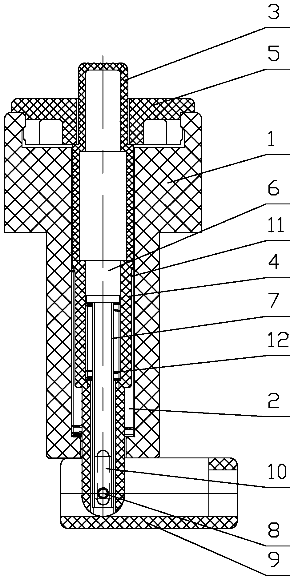
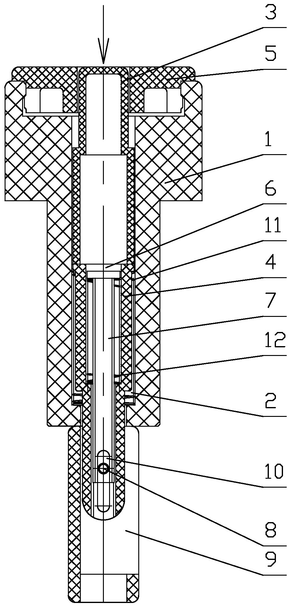
[0021] Such as Figure 1-4 As shown, a laminating machine table automatic pad, including:

[0022] A pad body 1, the inside of which is provided with a cavity A2;

[0023] Movable sleeve, the movable sleeve is movably installed in the cavity A2, and the cavity A2 is provided with a restricting part that cooperates with the movable sleeve to prevent the movable sleeve from breaking away from the cavity A2, and the upper and lower ends of the movable sleeve extend to the cavity respectively. On the outside of the cavity A2, there is a reset part in the cavity A2 to make the movable sleeve receive upward elastic force all the time, and a cavity B6 is arranged in the movable sleeve;

[0024] Pull pin 7, said pull pin 7 is arranged in the cavity B6, and the ...


PUM


Abstract

An automatic cushion block for a workbench of a film laminating machine comprises a cushion block body, a movable sleeve, and a pull pin; a cavity A is formed in the cushion block body; the movable sleeve is movably mounted in the cavity A, a limiting part matched with the movable sleeve to prevent the movable sleeve from being separated from the cavity A is arranged in the cavity A, the upper endand the lower end of the movable sleeve extend to the outer side of the cavity A respectively, a reset component enabling the movable sleeve to bear upward elastic force all the time is arranged in the cavity A, and a cavity B is formed in the movable sleeve; the pull pin is arranged in the cavity B, the bottom of the pull pin is connected with an ejector block at the bottom of the cushion blockbody through a rotating shaft, a tensioning component enabling the ejector block and the bottom of the cushion block body to be attached together all the time is arranged in the cavity B, and the rotating shaft moves up and down in a kidney-shaped groove in the bottom of the movable sleeve. The automatic cushion block is smooth to move and not easy to lag, the ejector block is good in in-place rotating effect, the deviation condition is avoided, internal parts are not prone to being damaged, the fault rate is low, the service life is long, and thus the production efficiency is improved.

Description

Technical field: [0001] The invention relates to an automatic cushion block of the working table of a laminating machine. Background technique: [0002] At present, when woodworking machinery and wood-based panels are laminated by ordinary laminating machines, the traditional way is to place the workpiece on the backing plate, requiring the size of the backing plate to be slightly smaller than the workpiece, so that a gap with a height difference is formed between the bottom surface of the workpiece and the working surface. Ensure that when the workpiece is covered with PVC film, the PVC film can cling to and cover the bottom surface of the workpiece over the bottom edge of the workpiece to ensure that the edge of the workpiece is smoothly in place. However, there are many types of workpieces and different sizes. Backing plates of different sizes are made for different workpieces, resulting in waste of resources, and frequent replacement of backing plates affects work effici...

Claims


Application Information

Patent Timeline
IPC IPC(8): B32B38/18
CPCB32B38/18
Inventor 孙波
Owner 济南展鸿图机械设备有限公司
Why Eureka
Try Eureka