An embedded power controller

A power controller, embedded technology, applied in the direction of electrical components, electrical equipment casing/cabinet/drawer, casing/cabinet/drawer components, etc., can solve the collision of surrounding objects, power controller damage, unconsidered to the power controller block and other issues

Active Publication Date: 2022-07-08
SHENZHEN TEKA TECH
View PDF7 Cites 0 Cited by
  • Summary
  • Abstract
  • Description
  • Claims
  • Application Information

AI Technical Summary

Problems solved by technology

[0003] Gantry cranes are set up in some workshops to realize the transportation and movement of materials, and when the materials are lifted, transported and moved, the materials will swing in any direction, and the corners of the materials may collide with surrounding objects, and the gantry cranes and the actual processing equipment need to be configured Power supply controller, if the power supply controller is installed with the convenience of personnel in mind, but does not take into account the obstruction of moving objects by the power supply controller exposed on the wall, that is, when the material is transported, the material may touch the power supply controller, causing damage to the power controller

Method used


Image

  • An embedded power controller
  • An embedded power controller
  • An embedded power controller

Examples


Embodiment 1

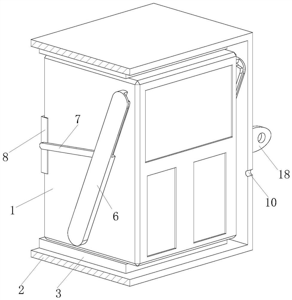
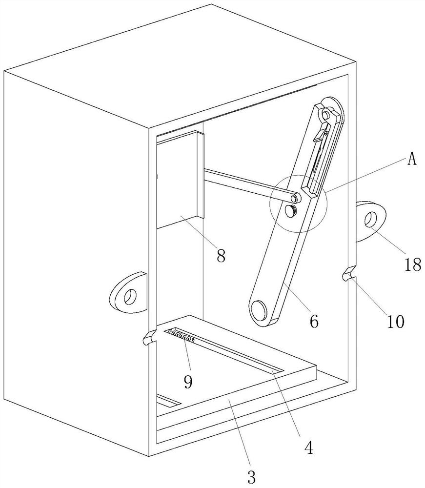
[0029] refer to Figure 1-7 , an embedded power supply controller, including a power supply controller body 1, the power supply controller body 1 is installed in a groove reserved on the wall through a box body 2; the box body 2 is provided with a substrate 3 and a pull Structure; the number of the base plate 3 is two, the upper and lower sides of the base plate 3 are respectively fixed on the inner top surface and the inner bottom surface of the box body 2, the base plate 3 is provided with a T-shaped groove 4, and the T-shaped groove 4 is slidably connected with a connection Block 5, the connection block 5 is fixedly connected to the upper top surface and the lower bottom surface of the power supply controller body 1;

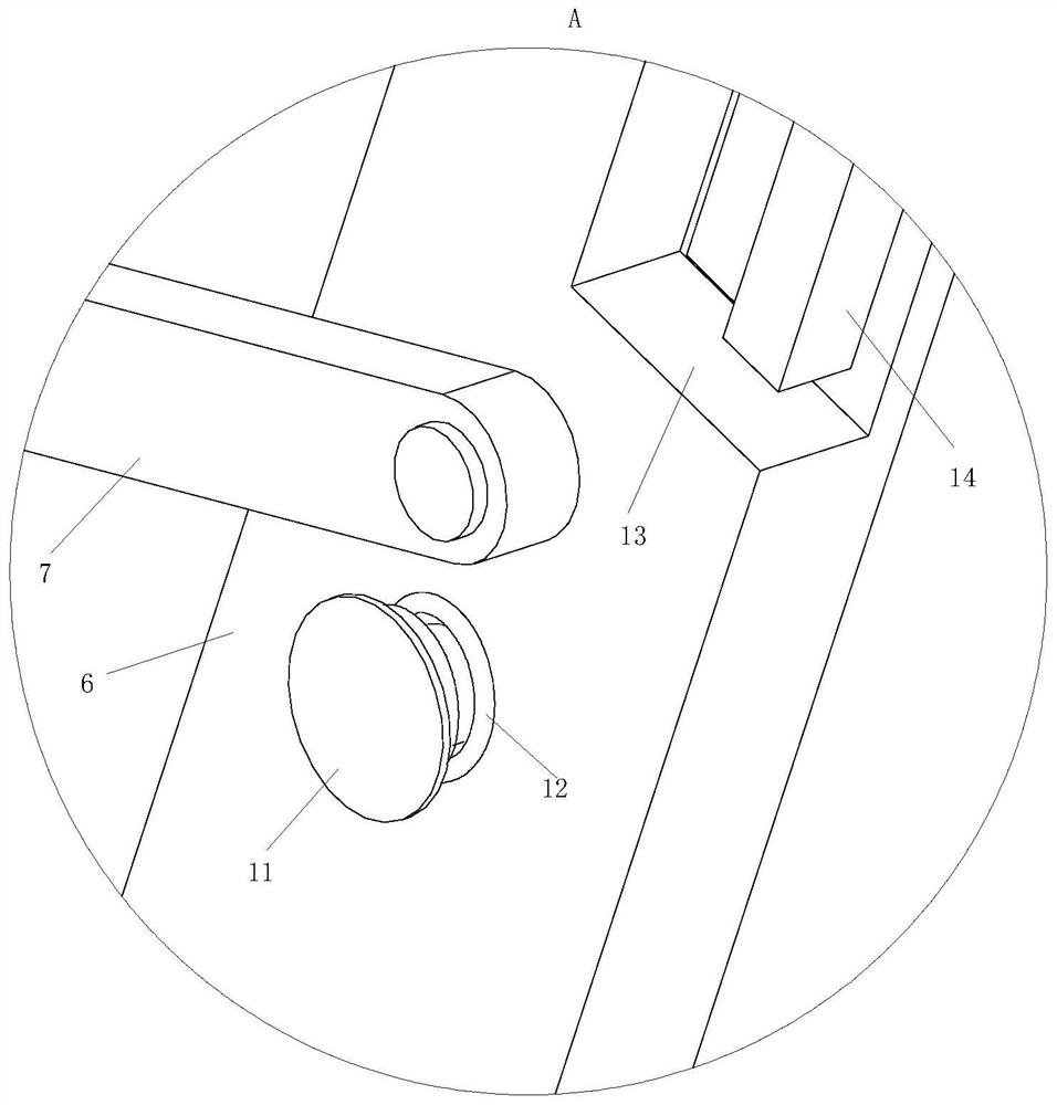
[0030] The two sides of the power controller body 1 are provided with a pulling structure No. 1 rod 6, No. 2 rod 7 and an L-shaped plate 8; The middle area of ​​6 is rotated to connect one end of the second pole 7, and the other end of the second pole 7 is r...

Embodiment 2

[0039] refer to Figure 8 , Comparative Example 1, as another embodiment of the present invention, wherein the inner side wall of the placement groove 16 is provided with a magnetic block 19, the magnetic block 19 adsorbs the support rod 17 in the placement groove 16, and then rotates the pull rod 14 to the concave portion 13. When inside, the support rod 17 needs to be rotated into the placement slot 16 first. By adsorbing the support rod 17 in the placement slot 16 , the support rod 17 is prevented from drooping vertically by itself, which affects the retraction of the pull rod 14 .

[0040] Working principle: Push the box body 2 into the groove, the outer port of the box body 2 is lower than the notch of the groove, some foam glue can be applied to the inner surface of the groove, the volume of the foam glue gradually increases, and the box body 2 is squeezed in the groove. In the groove, the power controller body 1 is assembled into the box body 2, so as to protect the pow...


PUM


Abstract

The invention belongs to the technical field of electrical appliances, in particular to an embedded power supply controller, comprising a power supply controller body, the power supply controller body is installed in a groove reserved on the wall through a box body; There is a base plate and a pulling structure; the number of the base plate is two, the upper and lower sides of the base plate are fixed to the inner top surface and the inner bottom surface of the box body respectively, a T-shaped groove is set on the base plate, and a connecting block is slidably connected in the T-shaped groove , the connection block is fixedly connected to the upper top surface and the lower bottom surface of the power supply controller body; the two sides of the power supply controller body are arranged with a pulling structure No. 1 rod, No. 2 rod and an L-shaped plate; one end of the No. 1 rod is rotatably connected At the position below the inner side wall of the box, the middle area of ​​the No. 1 rod rotates to connect with one end of the No. 2 rod, and the other end of the No. 2 rod rotates to connect to the L-shaped plate, and the inner corner of the L-shaped plate is attached to the rear wall of the power controller body. corner position.

Description

technical field [0001] The invention belongs to the technical field of electrical appliances, in particular to an embedded power controller. Background technique [0002] The power controller is used to control the electrical equipment and ensure the normal operation of the electrical equipment. [0003] In some workshops, gantry cranes are erected to realize the handling and movement of materials. When the materials are lifted, transported and moved, the materials will swing in any direction, and the edges and corners of the materials may collide with surrounding objects. The gantry cranes and the actual processing equipment need to be equipped Power controller, if the power controller is installed considering the convenience of personnel manipulation, but not considering the blocking of moving objects by the power controller exposed on the wall, that is, when the material is transported, the material may touch the power source controller, causing damage to the power contr...

Claims


Application Information

Patent Timeline
Patent Type & Authority Patents(China)
IPC IPC(8): H05K5/02
CPCH05K5/0234H05K5/0217
Inventor 何超肖国兴郑军
Owner SHENZHEN TEKA TECH
Why Eureka
Try Eureka