Single-time anti-infection type injection needle

An injection needle and infection prevention technology, applied in the field of medical devices, can solve the problems of patients prone to infection and poor response, and achieve the effects of improving effectiveness, reducing infection and improving safety.

Active Publication Date: 2021-09-03
永康市第一人民医院
View PDF7 Cites 1 Cited by
  • Summary
  • Abstract
  • Description
  • Claims
  • Application Information

AI Technical Summary

Problems solved by technology

[0006] In order to make up for the deficiencies of the existing technology and solve the problem that patients repeatedly use the same type of needle in order to save costs, causing patients to be prone to infection or adverse reactions during the injection process Problem, the present invention provides a single anti-infection injection needle

Method used


Image

  • Single-time anti-infection type injection needle
  • Single-time anti-infection type injection needle
  • Single-time anti-infection type injection needle

Examples


Embodiment 1

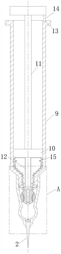
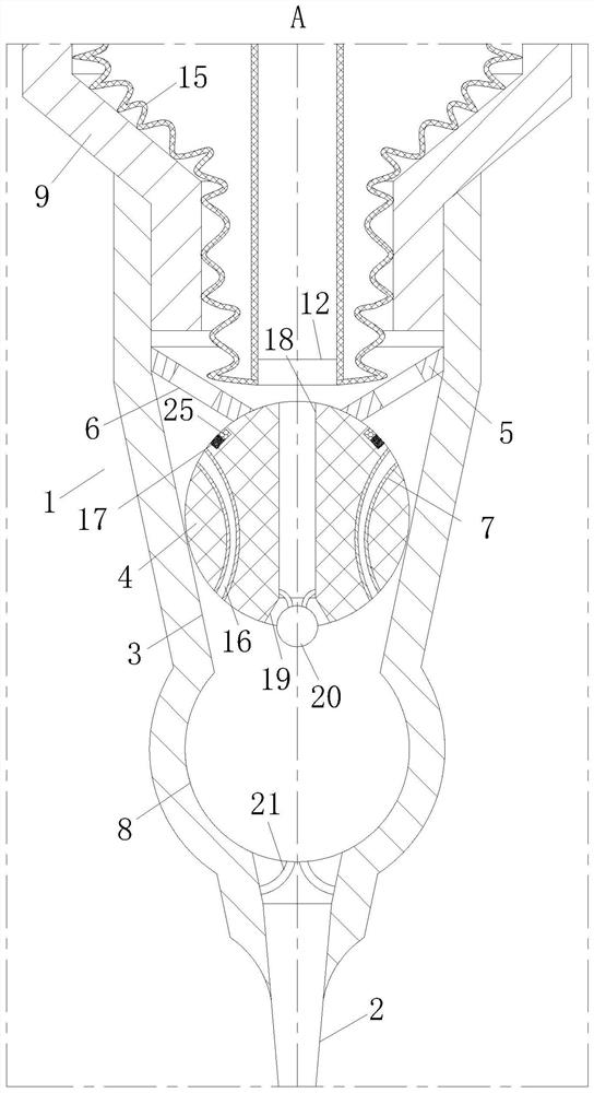
[0025] see Figure 1-2As shown, a single anti-infection injection needle according to the present invention includes a needle cover 1 and a puncture needle 2 installed on the needle cover 1; the bottom end of the needle cover 1 is provided with a tapered Cavity 3, the middle part of the tapered cavity 3 is clamped with a spherical elastic block 4, and the side wall of the tapered cavity 3 corresponding to the top of the elastic block 4 is provided with a limiting part 5, and the limiting part 5 can hold the elastic The block 4 is pressed against the side wall of the conical cavity 3, the limiting portion 5 is provided with a flow groove 6, and the elastic block 4 is provided with a set of vertically extending The flow hole 7, the side wall of the tapered cavity 3 corresponding to the bottom end of the elastic block 4 is provided with a snap-fit ​​cavity 8 matching its shape, when the elastic block 4 is pressed into the snap-fit ​​cavity 8, the snap-fit ​​cavity The side wall ...

Embodiment 2

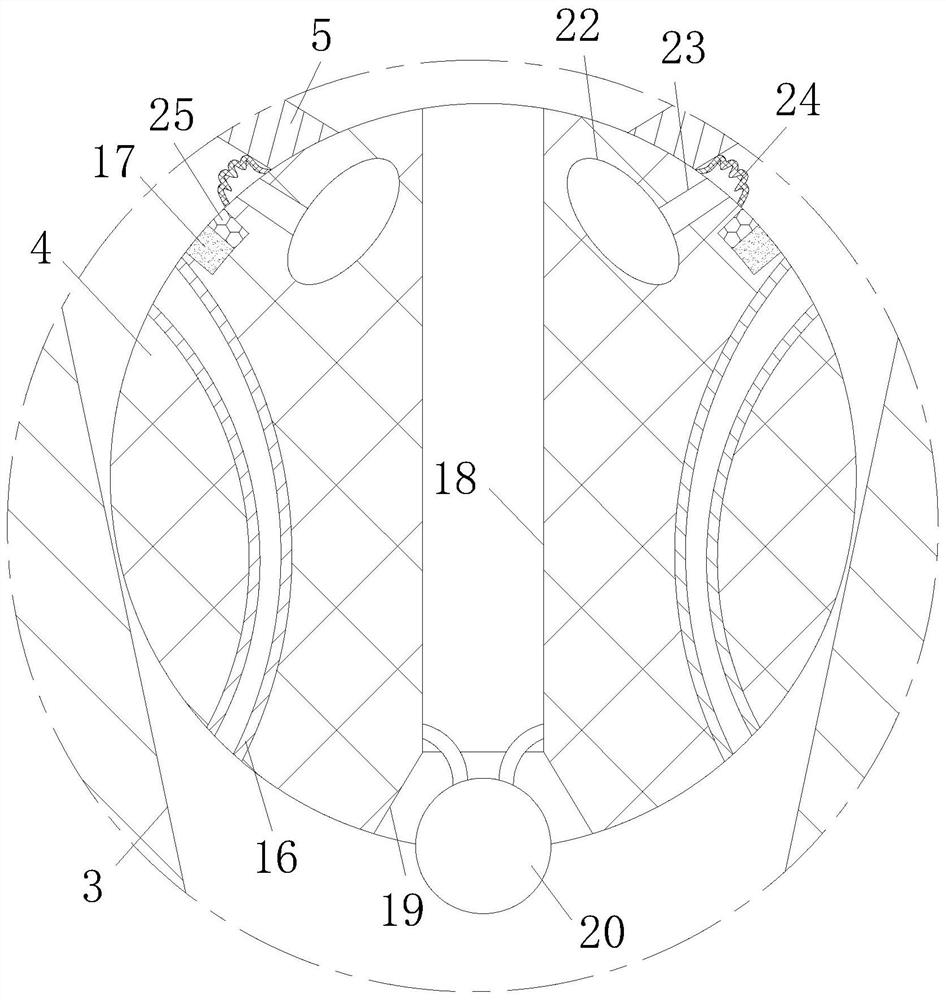
[0033] see image 3 As shown, the top of the elastic block 4 is provided with a group of cavities 22, and the outer surface of the elastic block 4 corresponding to the bottom end of the limiting part 5 is provided with an air channel 23 communicating with the cavity 22. The air channel 23 The outer surface of the elastic block 4 corresponding to the outer end is connected with a sealing film 24; during operation, when the pressure rod 12 squeezes the top of the elastic block 4, the cavity 22 can press the internal gas through the air channel 23 when it is compressed. Into the chamber between the sealing film 24 and the elastic block 4, so that the sealing film 24 can squeeze the liquid in the bottom chamber of the stopper 5 to fully flow out when the sealing film 24 bulges, further reducing the waste of medicinal liquid.

[0034] Working principle: Before insulin is injected, the elastic block 4 is clamped in the tapered cavity 3 between the limiting part 5 and the clamping ca...


PUM


Abstract

The invention relates to the technical field of medical instruments, and particularly relates to a single-time anti-infection type injection needle. The single-time anti-infection type injection needle comprises a needle sleeve and a puncture needle, wherein a conical cavity is formed in the bottom end of the needle sleeve, a spherical elastic block is clamped in the middle of the conical cavity, a limiting part is arranged on the side wall of the conical cavity, a circulation groove is formed in the limiting part, a set of circulation holes are formed in the outer surface of the elastic block, a clamping cavity is formed in the side wall of the conical cavity, a needle cylinder is connected to the top end of the needle sleeve, a piston is connected into the needle cylinder in a sliding mode, a push rod is fixedly connected to the top end of the piston, and a pressing rod is connected to the middle of the bottom end of the piston. By arranging the structure inside the needle, the purpose that the needle is automatically scrapped after injection is completed is achieved, the single-time injection effect of the needle is achieved, the problems of infection and the like caused by repeated use of the needle by a patient are reduced, and the safety of the injection needle in use is improved.

Description

technical field [0001] The invention relates to the technical field of medical devices, in particular to a single anti-infection injection needle. Background technique [0002] Suffering from diabetes, many patients need to inject insulin several times a day, usually after eating, so they need to carry insulin syringes with them wherever they go, and there are many different structures of insulin syringe designs. [0003] There are also some technical solutions on injection needles in the prior art, such as a Chinese patent with a patent number of 2017113229135, which proposes a needle for insulin injection, which is characterized in that it includes a front outer sheath (1) , the rear outer sheath (2), the rear outer sheath (2) is provided with a rear sealing plug (3), and the front outer sheath (1) is provided with a puncture needle (4); the front outer sheath (2) is provided with a puncture needle (4); The rear end of the sleeve (1) is connected to the rear outer sheath ...

Claims


Application Information

Patent Timeline
Patent Type & Authority Applications(China)
IPC IPC(8): A61M5/32A61M5/315A61M5/178
CPCA61M5/3278A61M5/31511A61M5/32A61M5/178A61M2005/328A61M2005/31516
Inventor 吕静平
Owner 永康市第一人民医院
Why Eureka
Try Eureka