
Ink-jet printer for computer part manufacturing

A technology of parts and computers, which is applied in the field of inkjet printers for computer parts manufacturing, can solve the problems of computer parts waste, inaccurate coding parts, easy to exceed the coding area, etc., and achieve good calibration and inkjet coding Precise, accurate printing effect

Inactive Publication Date: 2021-09-03
苏辉
View PDF0 Cites 0 Cited by
  • Summary
  • Abstract
  • Description
  • Claims
  • Application Information

AI Technical Summary

Problems solved by technology

[0003] However, the coding of existing computer parts uses manual and assembly line cooperation to complete the coding process, and it is easy to exceed the coding area during the coding process, the coding position is not accurate, and the parts on the assembly line are easy to shift when moving , resulting in scrapped computer parts

Method used


Image

  • Ink-jet printer for computer part manufacturing
  • Ink-jet printer for computer part manufacturing
  • Ink-jet printer for computer part manufacturing

Examples


Embodiment Construction

[0024] The following will clearly and completely describe the technical solutions in the embodiments of the present invention with reference to the accompanying drawings in the embodiments of the present invention. Obviously, the described embodiments are only some, not all, embodiments of the present invention. Based on the embodiments of the present invention, all other embodiments obtained by persons of ordinary skill in the art without making creative efforts belong to the protection scope of the present invention.

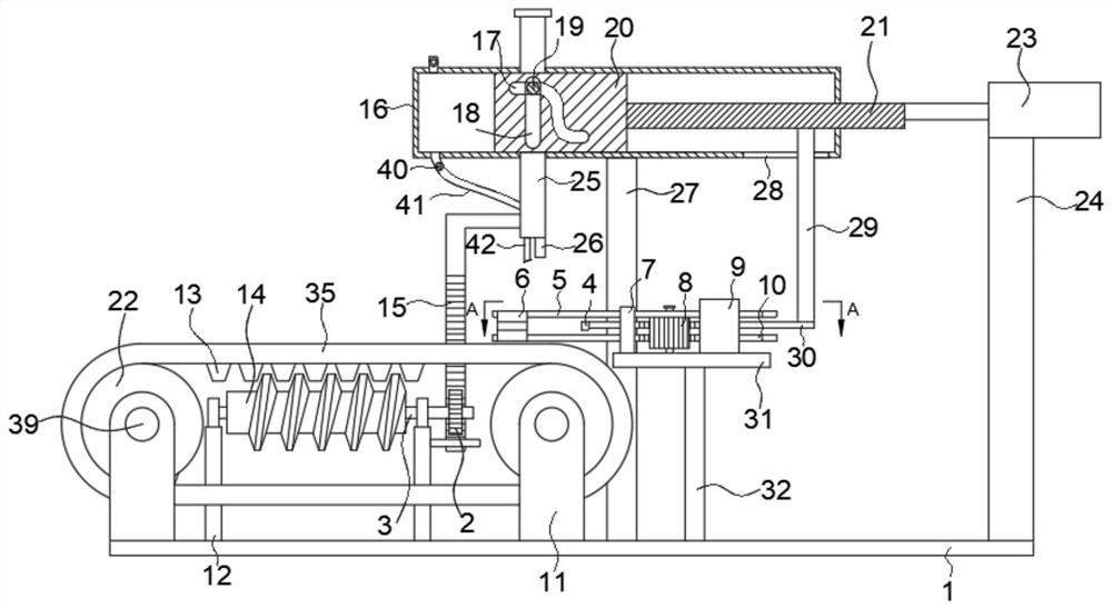
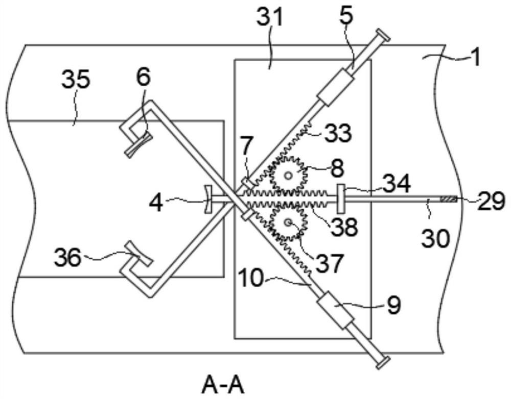
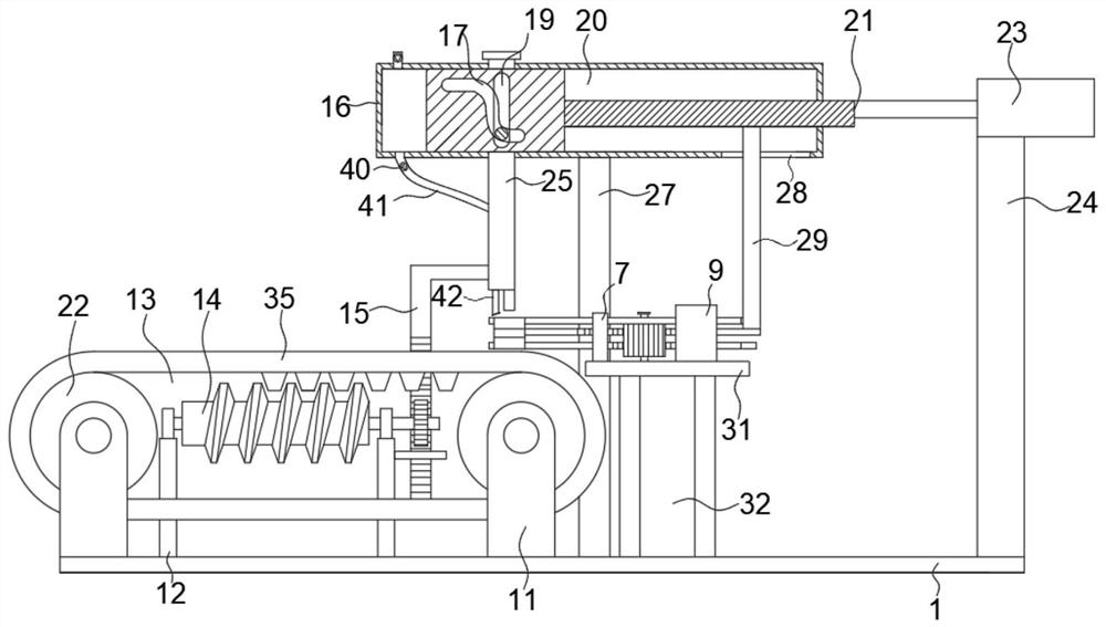
[0025] see Figure 1 to Figure 3 , the present invention provides a technical solution: an inkjet printer for computer parts manufacturing, including a bottom plate 1, the top of the bottom plate 1 is fixedly connected with a first support base 24, a third support base 32 and a second support base from right to left in sequence. Support base 27, the top of the second support base 27 is fixedly connected with installation box 16, and the upper and lower surface...


PUM


Abstract

The invention discloses an ink-jet printer for computer part manufacturing. The ink-jet printer comprises a bottom plate, the top of the bottom plate is fixedly connected with a first supporting seat, a third supporting seat and a second supporting seat in sequence from right to left, the top of the second supporting seat is fixedly connected with a mounting box, grooves are formed in the upper surface and the lower surface of the mounting box, a first transmission rod is vertically and slidably connected in the grooves, an inkjet printing head is mounted at the bottom of the first transmission rod, a transmission mechanism enabling the inkjet printing head to move up and down is arranged on the inner wall of the mounting box, a driving mechanism used for driving the transmission mechanism is arranged at the top of the first supporting seat, a calibration mechanism is arranged at the top of the third supporting seat, a material returning mechanism is arranged below the position, at the top of the bottom plate, of the inkjet printing head, and a cleaning mechanism used for cleaning the inkjet printing position is arranged at the bottom of the first transmission rod. According to the ink-jet printer, through cooperation of the above structures, the inkjet printing area of a part can be calibrated and fixed while automatic inkjet printing is achieved, and the inkjet printing procedure is more accurate.

Description

technical field [0001] The invention relates to the technical field of computer component processing, in particular to an inkjet printer for computer component manufacturing. Background technique [0002] For computer components, such as keyboards, outer casings, mice, rear casings, display casings, computer bases, etc., after processing, it is generally necessary to spray code on them in order to identify the precautions for use or the brand. Record, and spray the factory information on the parts. [0003] However, the coding of existing computer parts uses manual and assembly line cooperation to complete the coding process, and it is easy to exceed the coding area during the coding process, the coding position is not accurate, and the parts on the assembly line are easy to shift when moving , resulting in waste of computer parts. [0004] Therefore, the present invention provides an inkjet printer for computer component manufacturing. Contents of the invention [0005...

Claims


Application Information

Patent Timeline
Patent Type & Authority Applications(China)
IPC IPC(8): B41J2/01B41J3/407B41J25/308B41J29/17
CPCB41J2/01B41J3/4073B41J25/308B41J29/17
Inventor 苏辉
Owner 苏辉
Learn More