Check patentability & draft patents in minutes with Patsnap Eureka AI!

Double-nut constraint type lock bolt structure

An anti-loosening bolt and double-nut technology, applied in the direction of nuts, bolts, screws, etc., can solve problems such as the threat of safe operation of the line and the easy loosening of the anti-loosening performance.

Pending Publication Date: 2021-09-03
CHINA ELECTRIC POWER RES INST +1
View PDF0 Cites 0 Cited by
  • Summary
  • Abstract
  • Description
  • Claims
  • Application Information

AI Technical Summary

Problems solved by technology

The running bolts of the transmission line are mainly double nuts + gasket anti-loosening bolts, and their anti-loosening performance is prone to loosening in harsh natural environments, which poses a potential threat to the safe operation of the line

Method used


Image

  • Double-nut constraint type lock bolt structure
  • Double-nut constraint type lock bolt structure

Examples


Embodiment 1

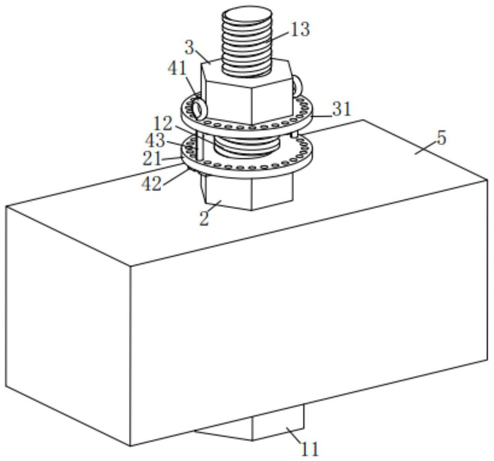
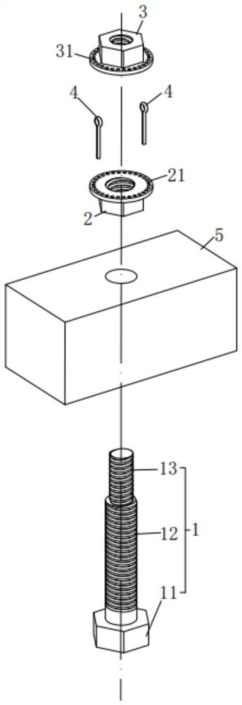
[0029] The present invention proposes a double-nut constrained anti-loosening bolt structure, such as figure 1 As shown, it includes a bolt 1, a main nut 2, a secondary nut 3 and a limit pin 4. The bolt 1 is composed of a bolt head 11, a first screw 12 and a second screw 13 fixedly connected in sequence, and the diameter of the first screw 12 is larger than that of the second screw. Two screw rods 13, the thread of the first screw rod 12 is opposite to the direction of rotation of the thread of the second screw rod 13, the main nut 2 is threaded with the first screw rod 12, the secondary nut 3 is threaded with the second screw rod 13, and the main nut 2 is provided with The main flange 21 and the auxiliary nut 3 are provided with an auxiliary flange 31, the main flange 21 and the auxiliary flange 31 are provided with holes, the limit pin 4 can be deformed, and inserted into the main flange 21 and the opening of the auxiliary flange 31 are used to prevent the relative rotation ...

Embodiment 2

[0034] The present invention proposes a double-nut constrained anti-loosening bolt structure, which can also be set as follows: the limit pin 4 is set as a "匚" type structure, and the perforated section 43 is pierced through the main flange 21 and the auxiliary flange 31. In the hole, the positioning section 41 is arranged on the side of the auxiliary flange 31 facing away from the main flange 21 , and the anti-off section 42 is arranged on the side of the main flange 21 facing away from the auxiliary flange 31 .

Embodiment 3

[0036] The present invention proposes a double-nut constrained anti-loosening bolt structure, which can also be set as follows: the perforated section 43 is arranged on the outside of the main flange 21 and the auxiliary flange 31, and the positioning section 41 is pierced through the auxiliary flange 31 In the hole on the main flange 21 , the anti-off section 42 is passed through the hole on the main flange 21 .


PUM


Abstract

A double-nut constraint type lock bolt structure comprises a bolt, a main nut, an auxiliary nut and a deformable limiting pin. The bolt is composed of a bolt head, a first screw rod and a second screw rod, the first screw rod is arranged between the bolt head and the second screw rod, and the diameter of the first screw rod is larger than that of the second screw rod. A main flange plate is arranged on the main nut. An auxiliary flange plate is arranged on the auxiliary nut. Holes are formed in the main flange plate and the auxiliary flange plate. After the main nut is screwed into the first screw rod and the auxiliary nut is screwed into the second screw rod, the limiting pin is inserted into the hole of the main flange plate and the hole of the auxiliary flange plate. According to the double-nut constraint type lock bolt structure, through cooperative constraint of the main flange plate on the main nut, the auxiliary flange plate on the auxiliary nut and the limiting pin, the main nut cannot rotate under the condition that the auxiliary nut is pre-tightened, and therefore the anti-loosening aim is achieved.

Description

technical field [0001] The invention relates to the technical field of mechanical engineering, in particular to a double-nut constraint type anti-loosening bolt structure. Background technique [0002] Tightening bolts can realize the connection between two structural parts, and the prerequisite is to ensure that the bolts cannot be relatively loose and rotated. The purpose of existing bolt anti-loosening technology is also to improve the stability of the mechanical structure and prevent running accidents due to bolt looseness. The running bolts of transmission lines are mainly anti-loosening bolts with double nuts and washers, and their anti-loosening performance is prone to loosening in harsh natural environments, which poses a potential threat to the safe operation of the line. Contents of the invention [0003] In order to solve the problem that the anti-loosening bolts with double nuts and gaskets are prone to loosening in harsh natural environments, the present inve...

Claims


Application Information

Patent Timeline
IPC IPC(8): F16B39/02F16B39/16
CPCF16B39/02F16B39/16
Inventor 顾建李冬青刘胜春司佳钧刘绪良蔡松林刘龙张军刘臻齐翼牛海军刘鹏张昭张暕
Owner CHINA ELECTRIC POWER RES INST
Features
  • R&D
  • Intellectual Property
  • Life Sciences
  • Materials
  • Tech Scout
  • Unparalleled Data Quality
  • Higher Quality Content
  • 60% Fewer Hallucinations
Learn More