Thread anti-loosening mechanism and anti-loosening mounting method

An installation method and thread technology, applied in the direction of threaded fasteners, screws, nuts, etc., can solve the problems of inability to quickly disassemble, inability to achieve anti-loosening, unreliability, etc., achieve reliable anti-loosening performance, prompt use flexibility, anti-loosening Reliable effect of loose measures

Pending Publication Date: 2022-01-28
GUIZHOU FENGLEI AVIATION ORDNANCE CO LTD
View PDF1 Cites 0 Cited by
  • Summary
  • Abstract
  • Description
  • Claims
  • Application Information

AI Technical Summary

Problems solved by technology

[0004] In view of the shortcomings of the existing thread anti-loosening methods that cannot be disassembled quickly, are unreliable, and cannot achieve anti-loosening at any screw position, the present invention provides a mechanism that can reliably anti-loosen the thread and realize quick disassembly

Method used


Image

  • Thread anti-loosening mechanism and anti-loosening mounting method
  • Thread anti-loosening mechanism and anti-loosening mounting method
  • Thread anti-loosening mechanism and anti-loosening mounting method

Examples


Embodiment Construction

[0017] The specific implementation manner of the present invention will be described in detail below according to the accompanying drawings.
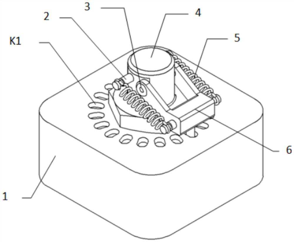
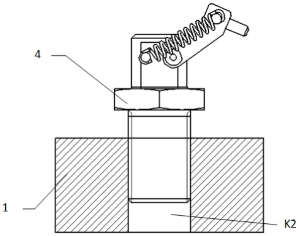
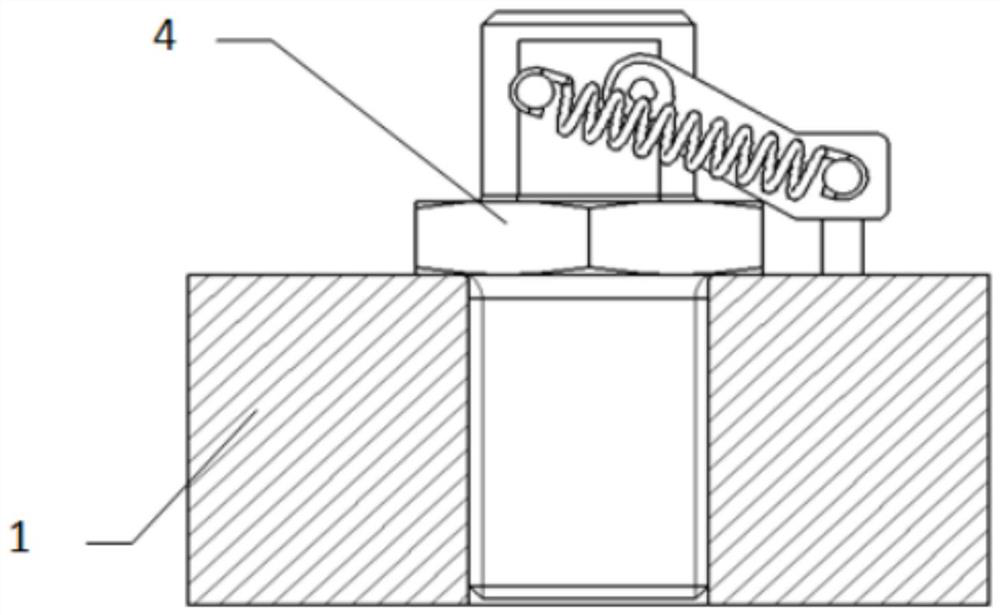
[0018] The overall design idea of ​​the present invention is to provide a fast-detachable thread anti-loosening mechanism by utilizing the spring fixed limit mechanism to carry out the thread anti-loosening and the design idea of ​​rotating past the dead point for quick disassembly. A concrete realization of a thread anti-loosening mechanism, the structural diagram is as follows figure 1 As shown, it is mainly composed of mounting base 1; pin shaft 2; hollow rivet 3; screw rod 4; On the mounting base 1, the upper surface of the mounting base 1 is provided with a circle of small holes K1 for inserting the rotating arm 6;

[0019] The screw 4 is in the shape of large and small steps, and the bottom of the screw 4 is provided with an external thread for connecting with the threaded hole K2; the middle of the screw is provided with an oute...


PUM


Abstract

The invention belongs to the field of mechanical installation, and particularly relates to a thread anti-loosening mechanism and an anti-loosening installation method. The mechanism comprises an installation base, a pin shaft, a screw rod, an extension spring and a rotating arm; a threaded hole for mounting the screw rod is formed in the installation base, and a plurality of small holes are uniformly distributed along the circumferential direction of the threaded hole; the screw rod can be mounted on the installation base through the threaded hole, and two sides of the upper end of the screw rod are designed into plane structures; one end of the rotating arm is of a double-lug structure, double lugs are rotationally installed on plane structures on the two sides of the upper end of the screw rod, and the rotating arm can rotate around the screw rod; the other end of the rotating arm is further provided with a limiting protrusion capable of being inserted into a small hole in the upper surface of the installation base; pin holes are further formed in the plane structures on the two sides of the upper end of the screw rod and used for installing the pin shaft, one end of the extension spring is installed on the pin shaft, the other end is installed on the rotating arm, the length of the spring is not smaller than the distance between the threaded hole and the small hole of the installation base, and when the rotating arm rotates by any angle, the spring has a certain extension limiting effect on the rotating arm; and any screwing-in position of the screw rod is in an anti-loosening state.

Description

technical field [0001] The invention belongs to the field of mechanical installation, and in particular relates to a thread anti-loosening mechanism and an anti-loosening installation method, which is a mechanism for anti-loosening of bolts after they are installed or fixed by bolts. Background technique [0002] At present, there are roughly three anti-loosening methods commonly used for existing threaded connections. One is the mechanical locking type, that is, the form of a fuse and the form of a cotter pin on the screw and the nut. This anti-loosening method cannot be quickly disassembled; the second type It is a free-rotating type, even if it is in the form of a spring washer, this anti-loosening method is not reliable enough in a vibration environment; the third type is the bonding type, that is, apply adhesive or punching points on the threaded section. The anti-loosening method is mostly used in occasions where disassembly is infrequent. For some special application...

Claims


Application Information

Patent Timeline
IPC IPC(8): F16B39/02
CPCF16B39/02
Inventor 孙江李刚潘忠军李伟
Owner GUIZHOU FENGLEI AVIATION ORDNANCE CO LTD
Why Eureka
Try Eureka