Oil-saving bubble atomization oil gun

A technology of oil gun and air bubbles, which is applied in the field of fuel-saving bubble atomization oil guns, and can solve the problems of easy blockage of oil and gas communication channels and unstable atomization effect

Pending Publication Date: 2021-09-03
襄阳市胜合燃力设备有限公司
View PDF1 Cites 0 Cited by
  • Summary
  • Abstract
  • Description
  • Claims
  • Application Information

AI Technical Summary

Problems solved by technology

[0006] Based on the above statement, the present invention provides a fuel-saving bubble atomization oil gun to solve the technical problems in

Method used


Image

  • Oil-saving bubble atomization oil gun
  • Oil-saving bubble atomization oil gun
  • Oil-saving bubble atomization oil gun

Examples


Embodiment 1

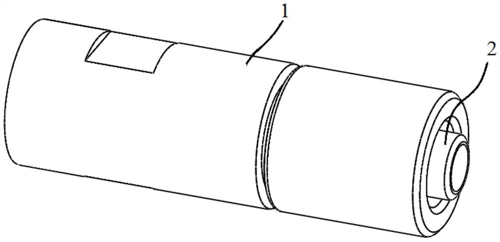
[0040] Such as Figure 1 to Figure 5 As shown, the present application provides a fuel-saving air bubble atomization oil gun, which includes a hollow outer tube 1 and an inner pipeline 2 .

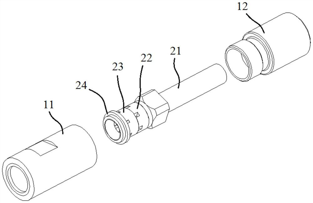
[0041] Wherein, the rear end of the hollow outer tube 1 has an air inlet 1a. In some embodiments, the hollow outer tube 1 can be a single integrated pipe. In a preferred embodiment, the hollow outer tube 1 includes The outer casing 11 and the outer adapter 12 installed in sequence are sealed in communication, wherein the outer casing 11 and the outer adapter 12 are preferably threaded.

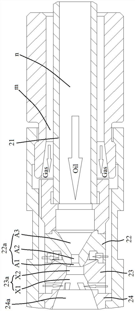
[0042] The inner pipeline 2 is coaxially built inside the hollow outer tube 1 , and an air flow channel m is formed between the hollow outer tube 1 and the inner pipeline 2 .

[0043] In this embodiment, the internal pipeline 2 includes a hollow inner tube 21, a spray head 22 and a first stopper 23, and the hollow inner tube 21 has an oil channel n inside and an oil inlet 21a at the rear end;

[0044] Wh...

Embodiment 2

[0056] Embodiment 2 of the present application provides a fuel-saving air bubble atomization oil gun, the overall structure of which is basically the same as that of Embodiment 1, where the difference lies in:

[0057] Such as Figure 6 and Figure 7 and combine image 3 As shown, the hollow inner tube 21 includes an oil pipe 211 installed in sealed communication and an inner adapter 212. A baffle 213 is formed inside the inner adapter 212. A hole is opened in the middle of the baffle 213. The oil pipe 211 is installed at the rear end of the baffle 213 .

[0058] The internal pipeline 2 also includes an oil mixing block 25, which is coaxially and rotatably installed inside the inner adapter 212 and is located at the front end of the baffle plate 213. The oil mixing block 25 Two oil mixing channels 25a connecting the front and rear ends of the oil mixing block 25 are formed on the outer side of the oil mixing block 25. The oil mixing channels 25a are evenly distributed along...


PUM


Abstract

The invention relates to an oil-saving bubble atomization oil gun which comprises a hollow outer pipe and an inner pipeline. The inner pipeline is coaxially arranged in the hollow outer pipe, an airflow channel is formed between the hollow outer pipe and the inner pipeline, the inner pipeline comprises a hollow inner pipe, a spray head and a first stop block, and an oil way channel is formed in the hollow inner pipe. The spray head is installed at the front end of the hollow inner pipe and comprises a base and a nozzle, the nozzle is coaxially installed on the base, a spraying channel is formed in the nozzle, the nozzle is connected to the front end of the hollow inner pipe in a sealed mode, an annular flange is formed on the edge of the front end of the base, a first air inlet cavity is formed between the annular flange and the nozzle, and a plurality of first air inlet channels are formed in the annular flange. The first stop block is installed at the front end of the spray head, an oil passing hole is formed in the first check block, and the spraying channel and the first air inlet cavity communicate with the oil passing hole. The multiple first air inlet channels are arranged around the annular flange, oil and gas communication is stable and reliable, the atomization effect is guaranteed, and fuel oil is saved.

Description

technical field [0001] The invention relates to the technical field of burner equipment, in particular to an oil-saving air bubble atomization oil gun. Background technique [0002] The ignition oil gun and auxiliary oil gun of the rotary kiln burner are traditionally used in the mechanical pressure atomizing oil gun. Mechanical atomization oil gun has a simple structure and is easy to use and operate, but its atomization effect is relatively poor. In addition to its structural characteristics, the outlet aperture is small (generally about Φ3.5mm), which is prone to coking and blockage, and cold furnace ignition Black smoke phenomenon. [0003] Bubble atomization technology is a brand-new atomization technology. Its atomization mechanism is to use the theory of fluid mechanics two-phase flow to inject low-pressure atomization medium (steam or compressed air) into low-pressure oil and mix it in a mixing chamber. Form the specific flow state of gas-in-oil—bubble flow, use th...

Claims


Application Information

Patent Timeline
IPC IPC(8): F23D11/10F23D11/36F23D11/38
CPCF23D11/10F23D11/36F23D11/38
Inventor 刘杰
Owner 襄阳市胜合燃力设备有限公司
Why Eureka
Try Eureka