
A led projection lamp

A technology of LED projection lamps and LED lamp beads, which is applied in lighting and heating equipment, fixed lighting devices, semiconductor devices of light-emitting elements, etc., can solve the problems of LED projection light flux decline, unclear projection patterns, etc., and achieve airtightness Good performance, stable and reliable connection, prolonging the service life

Active Publication Date: 2019-01-25
广东盛世飞扬光电科技有限公司
View PDF4 Cites 0 Cited by
  • Summary
  • Abstract
  • Description
  • Claims
  • Application Information

AI Technical Summary

Problems solved by technology

Due to the particle dust attached to the air in the surrounding environment during the operation of the product, a large amount of particle dust enters the inner cavity of the LED lamp bead and lens combination, resulting in a gradual decrease in the luminous flux of the LED projection lamp and unclear projection patterns.

Method used


Image

  • A led projection lamp
  • A led projection lamp
  • A led projection lamp

Examples


Embodiment 1

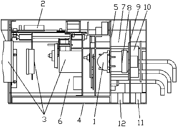
[0021] Such as figure 1 As shown, an LED projection lamp includes an LED lamp bead 1, an LED driver board 2, a lens group 3 and a housing 4, the LED lamp bead 1 is electrically connected to the LED driver board 2, and the LED lamp bead 1, the LED driver board 2 and The lens groups 3 are all bonded to the housing 4, and the housing 4 is provided with a partition 5, and the partition 5 divides the interior of the housing 4 into a cavity 6 and a heat dissipation cavity 7. The LED lamp bead 1, the LED driver board 2 and the lens group 3 are located in the cavity 6, the heat dissipation chamber 7 is provided with a radiator 8, a fan frame 9 and a fan 10, and the radiator 8 and the LED lamp bead 1 are respectively located on the front of the partition 5 and On the opposite side, the radiator 8 and the LED lamp bead 1 are respectively bonded to the partition 5, the fan 10 is installed on the fan frame 9, and the housing 4 is provided with an air inlet 11 and an air outlet 12, so that...

Embodiment 2

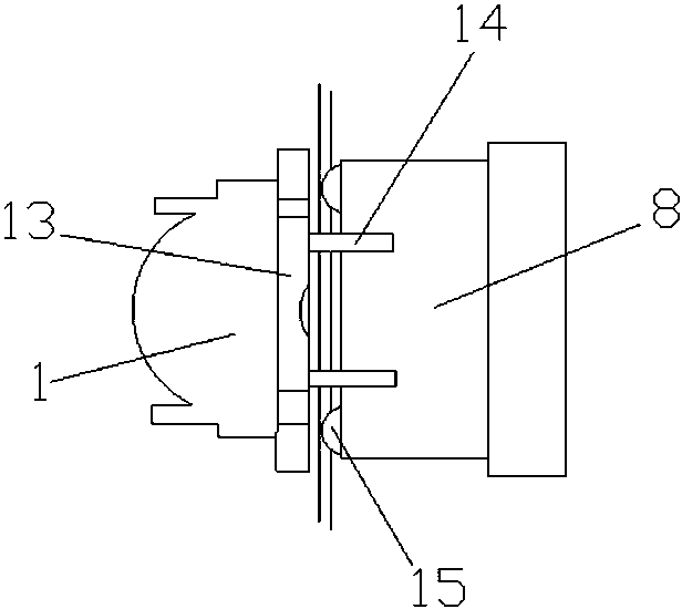
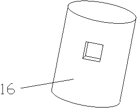
[0024] Such as Figure 1-3As shown, an LED projection lamp includes an LED lamp bead 1, an LED driver board 2, a lens group 3 and a housing 4. A partition 5 is arranged inside the housing 4, and the LED lamp bead 1 is electrically connected to the LED driver board 2. The LED lamp bead 1, the LED driver board 2 and the lens group 3 are all bonded to the housing 4, and the partition 5 divides the inside of the housing 4 into a cavity 6 and a heat dissipation chamber 7. The LED lamp bead 1, the LED driver board 2 and the lens group 3 are located in the cavity 6, the heat dissipation chamber 7 is provided with a radiator 8, a fan frame 9 and a fan 10, and the radiator 8 and the LED lamp bead 1 are respectively located on the front of the partition 5 and On the opposite side, the fan 10 is installed on the fan frame 9 , and the housing 4 is provided with an air inlet 11 and an air outlet 12 , and the air inlet 11 and the air outlet 12 are both connected to the cooling cavity 7 . T...


PUM


Abstract

The invention discloses an LED projection lamp. The LED projection lamp comprises an LED lamp bead, an LED driving board, a lens assembly and a casing, wherein a partition board is arranged in the casing and divides the inner part of the casing into a hollow cavity and a heat dissipation cavity; the LED lamp bead, the LED driving board and the lens assembly are located in the hollow cavity; a heat dissipation device, a fan rack and a fan are arranged in the heat dissipation cavity; the heat dissipation device and the LED lamp bead are located on the front surface and the back surface of the partition board respectively; the fan is mounted on the fan rack; an air inlet and an exhaust port are formed in the casing and are both communicated with the heat dissipation cavity. The LED projection lamp cannot be influenced by attached particles and dust in air in the ambient environment during using.

Description

technical field [0001] The invention relates to an LED projection lamp. Background technique [0002] LED projection lamp is a device used to project patterns onto curtains or other backgrounds for display, and is widely used in places such as people's lives or work. [0003] The air inlet and outlet of the heat dissipation design of the LED projection lamp are in the internal space of the combination of LED lamp beads and lenses, and the combination of LED lamp beads, electronic components, and lenses becomes a channel for air convection. Due to the attachment of particulate dust in the air of the surrounding environment during the operation of the product, a large amount of particulate dust has entered the inner cavity of the LED lamp bead and lens combination, resulting in a gradual decrease in the luminous flux of the LED projection lamp and unclear projection patterns. The accumulation of particulate dust, which becomes the electrolyte of electronic components, gradual...

Claims


Application Information

Patent Timeline
Patent Type & Authority Patents(China)
IPC IPC(8): F21S8/00F21V5/04F21V29/67F21V31/00F21Y115/10
CPCF21S8/00F21V5/04F21V29/673F21V31/00F21V31/005
Inventor 杨建新
Owner 广东盛世飞扬光电科技有限公司
Learn More