
Electrical switch with self-locking function

A technology of electrical switches and switches, applied in the direction of electrical components, circuits, parts of connecting devices, etc., can solve problems such as difficulty in realizing automatic locking, difficulty in long-term stable operation of electrical equipment, and poor convenience in operation and use, and achieve reasonable structural design , Convenient and efficient detachment, efficient and convenient installation and clamping effect

Active Publication Date: 2020-08-07
嘉兴市平安电气工程有限公司
View PDF8 Cites 0 Cited by
  • Summary
  • Abstract
  • Description
  • Claims
  • Application Information

AI Technical Summary

Problems solved by technology

The existing commonly used electrical switches mainly include knife switches and push switches. The self-locking effect of the knife switches and push switches is poor, and it is difficult to ensure that the circuit is continuously and reliably connected. When touched, it is easy to cause an open circuit, resulting in difficulty in electrical equipment. Long-term stable operation
In order to achieve a continuous and stable connection circuit of the electrical switch, the electrical switch is required to have a conduction locking function, that is, to lock when the electrical switch is closed and conduction, so that the electrical switch remains in the conducting state. The existing electrical switch with the conduction locking function The structure of the switch is complex and the operation is troublesome. The locking mechanism of the electrical switch has poor locking stability. It is difficult to realize automatic locking when the electrical switch is closed and connected. The operation and use are poor and difficult to meet the needs of use.

Method used


Image

  • Electrical switch with self-locking function
  • Electrical switch with self-locking function
  • Electrical switch with self-locking function

Examples


Embodiment Construction

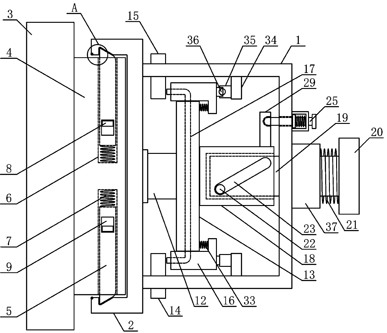
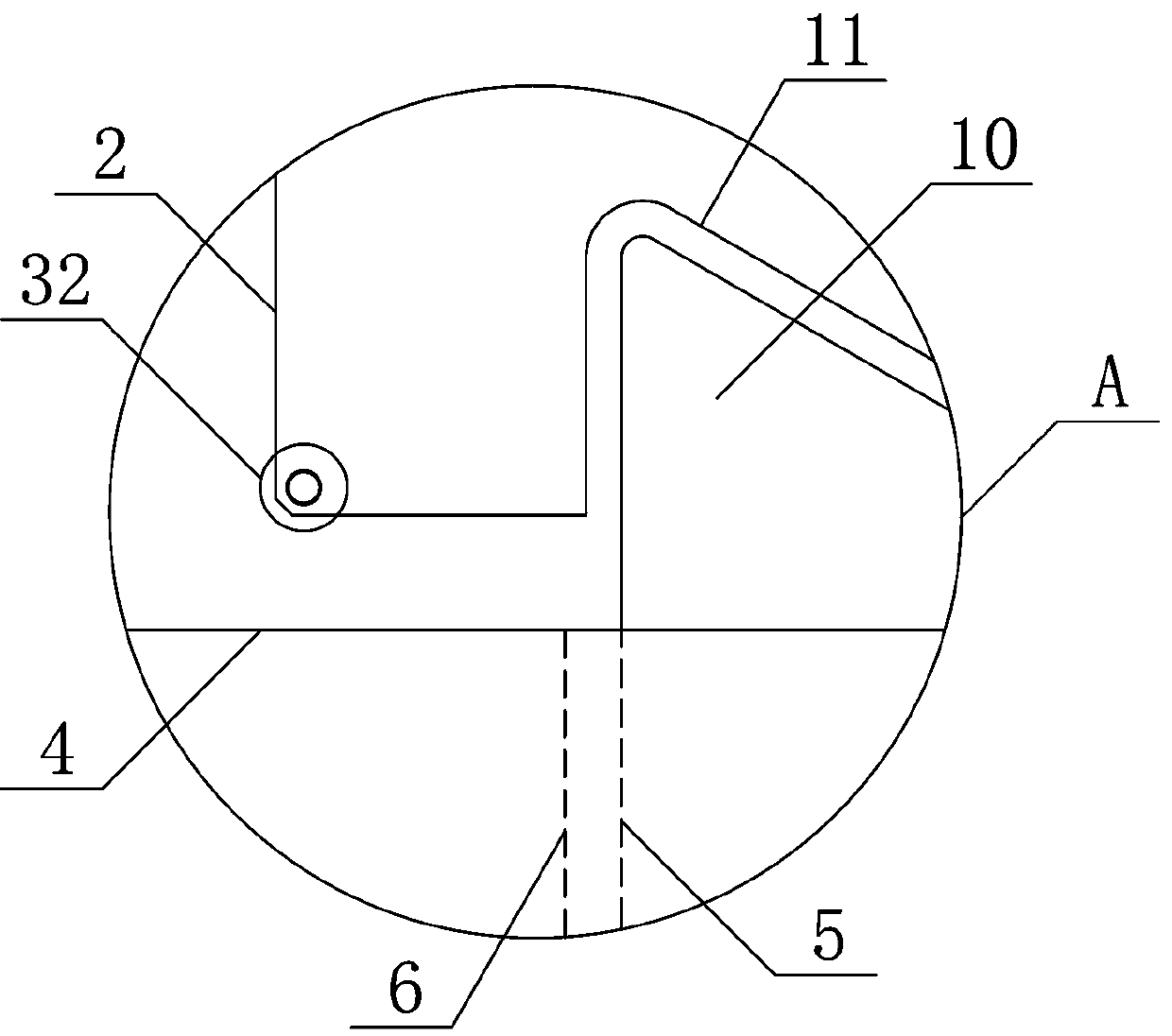
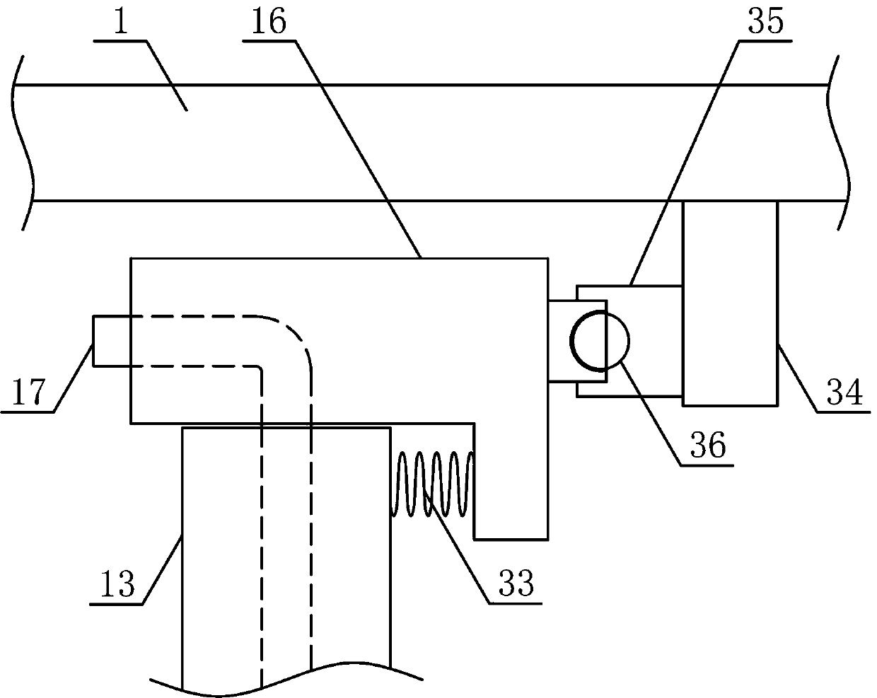
[0015] In order to further describe the present invention, a specific implementation of an electrical switch with self-locking function will be further described below in conjunction with the accompanying drawings. The following examples are explanations of the present invention and the present invention is not limited to the following examples.

[0016] Such as figure 1 As shown, a kind of electric switch with self-locking function of the present invention comprises switch insulating box 1, insulating box base 2, electric switch base 3 and installation connection seat 4, and installation connection seat 4 is fit and fixedly arranged on electric switch base 3- side, the insulating box base 2 is fixedly arranged on the bottom of the switch insulating box 1, the insulating box base 2 is clamped on the installation connection seat 4, and the two sides of the installation connection seat 4 are respectively symmetrically slid to install the installation lever 5, and the installation...


PUM


Abstract

The invention discloses an electrical switch with a self-locking function, and belongs to the technical field of electrical element equipment. According to the electrical switch, a mounting connectingseat is fixedly arranged on one side of an electrical switch base in an attached mode; an insulation box base is fixedly arranged at the bottom of a switch insulation box; the insulation box base isclamped on the mounting connecting seat; two sides of the switch insulation box are respectively provided with a wire inlet joint and a wire outlet joint; two ends of a switch connecting conducting wire arranged in a reciprocating rotating plate penetrate through conducting wire connecting plates arranged on the two sides of the reciprocating rotating plate respectively; the end of a switch pressing rod is arranged in the inner cavity of a reciprocating rotating bush in a sliding mode; a locking ejector rod is arranged on one side of the switch pressing rod in parallel; and a positioning rotating plate is fixedly arranged on the reciprocating rotating bush along the switch insulation box end. The electric switch is reasonable in structural design, convenient to operate and use, capable ofbeing automatically locked when the electric switch is closed and connected, capable of keeping stable and reliable conduction when the electric switch is connected and used, high in safety, high in practicability and capable of meeting use requirements.

Description

technical field [0001] The invention belongs to the technical field of electrical component equipment, and in particular relates to an electrical switch with a self-locking function. Background technique [0002] With the development of the electric power industry, various electrical products are widely used in various fields of industry and civil use. Electrical connectors are currently the main electrical components used to connect electrical circuits, mainly including electrical switches, power plugs and power terminals. When electrical equipment is used, it is generally necessary to use an electrical switch. An electrical switch is generally a switch used to control an electrical circuit. The electrical switch can make the circuit conduct and realize the normal operation of the electrical equipment. The switch that frequently turns on and off the circuit manually, or as the introduction switch of the power supply in the machine tool circuit, is divided into knife switch,...

Claims


Application Information

Patent Timeline
Patent Type & Authority Applications(China)
IPC IPC(8): H01R13/631H01R13/639
CPCH01R13/631H01R13/639
Inventor 方芳钱亚婧李国伟
Owner 嘉兴市平安电气工程有限公司
Learn More