Wire switching apparatus

A transfer device and wire transfer technology, which is applied to the parts of the connection device, coupling devices, circuits, etc., can solve the problems of multi-strand wires easy to scatter, connection failure, burning equipment, etc., and achieve good compression connection ability , The use state is stable and reliable, and the effect of firm and reliable connection

Active Publication Date: 2016-02-03
GUANGZHOU PANYU CABLE WORKS
View PDF7 Cites 11 Cited by
  • Summary
  • Abstract
  • Description
  • Claims
  • Application Information

AI Technical Summary

Problems solved by technology

[0004] 1. The interface does not match
Due to the different specifications of the wires that need to be connected, the diameters of the wires vary, and the connection structures of various electrical equipment or electromechanical products tend to be standardized (that is, a certain type of product usually only provides one cable connection interface), it is difficult to To adapt to the connection requirements of cables of different specifications in the market and applications, in practice, it often happens that thick cables are connected to thin wiring holes or thin cables are connected to thick wiring holes—both wiring efficiency and connection quality will be affected; moreover, Due to the different diameters of the wires that need to be connected, the area or connection quality of the electrical connection established by it also shows a large difference-thin wires have a small electrical contact area, and thick wires have a large electrical connection area
[0005] 2. When the cable to be connected is a multi-strand wire, due to the action of the compression screw and/or the twisting during assembly, the multi-strand wires that are hinged together are very easy to scatter, which will cause tension between the cable and the terminal. el

Method used


Image

  • Wire switching apparatus
  • Wire switching apparatus
  • Wire switching apparatus

Examples


Embodiment 1

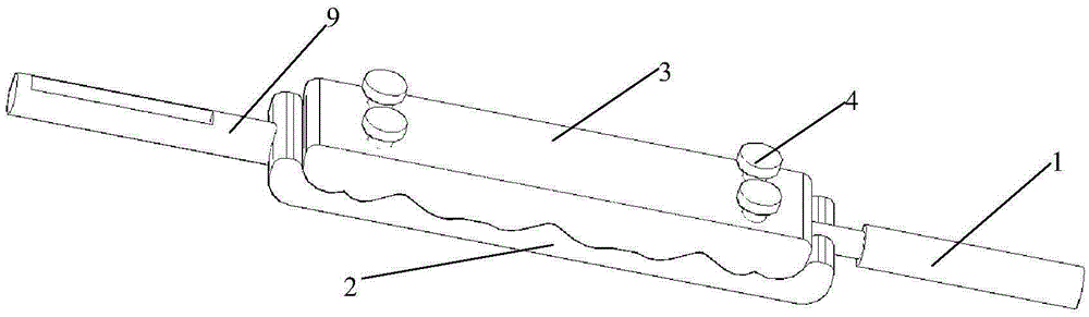
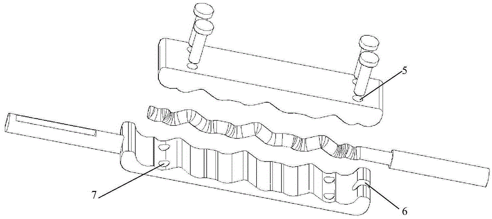
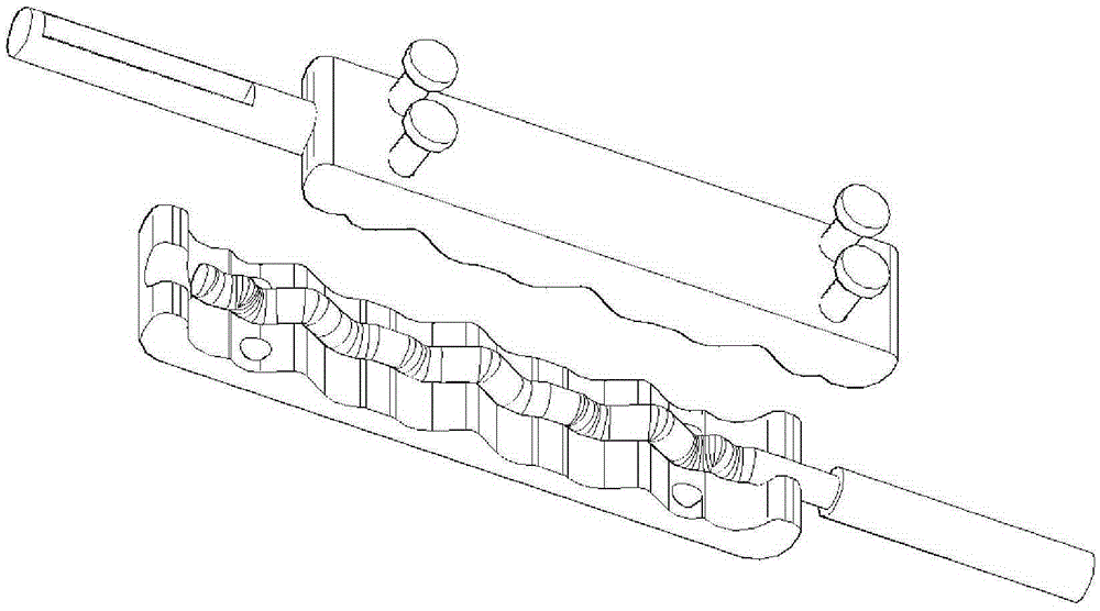
[0042] like figure 1 , 2 As shown, a wire transfer device includes a transfer device body 2 and a pressing block 3 and a locking device for detachably connecting the transfer device body 2 and the pressing block 3, and a surface of the transfer device body 2 is provided There is a concave-convex crimping structure. Correspondingly, one surface of the pressure block 3 is provided with a concavo-convex crimping structure that matches it, and one end of the adapter body 2 is provided with a plug-in terminal 9 for use with a wire insertion hole; another example image 3 , 6 As shown, one end of the pressing block 3 is provided with a plug-in terminal 9 for use in conjunction with the wire insertion hole; the other end of the adapter body 2 or the pressing block 3 is provided with a limiting structure to prevent the wire from sliding laterally; The connecting terminal 9 is set in the wire insertion hole of the wiring structure on the electric equipment or the electromechanical ...

Embodiment 2

[0047] On the basis of the technical solution of the wire transfer device described in Embodiment 1, the following improvements have been further made:

[0048] like figure 1 , 2 As shown, the locking device includes a locking screw 4; the pressing block 3 and the adapter body 2 are respectively provided with a first through hole 5 and a second through hole 7; the first through hole 5 and the second through hole The two through holes 7 are all light holes, and the locking screw 4 passes through the first through hole 5 and the second through hole 7 to cooperate with a locking nut, so that the adapter body 2 and the pressure block 3 can be connected. Disconnect and lock,

[0049] Or one of the first through hole 5 and the second through hole 7 is a light hole, and the other through hole is a screw hole that can cooperate with the locking screw 4, and the locking screw 4 passes through the light hole and the screw in turn. hole, so that the detachable connection and lock of ...

Embodiment 3

[0052] On the basis of the technical solution of the wire transfer device described in embodiment 1 or 2, the following improvements have been further made:

[0053] like Figure 13 As shown, the adapter body 2 or the pressing block 3 are provided with contact-type thermistors, thermal switches or non-contact infrared light temperature sensors, ultraviolet light temperature sensors 11, the thermistors, thermal The monitoring signal obtained by the sensitive switch or temperature sensor is transmitted to the upper monitoring system in a wired or wireless manner.


PUM


Abstract

The invention discloses a wire switching apparatus. The wire switching apparatus comprises a switching apparatus body, a pressure block, and a locking apparatus for detachable connection with the switching apparatus body and the pressure block. One surface of the switching apparatus body is provided with a concave-convex pressing line structure, correspondingly, one surface of the pressure block is provided with a matched concave-convex pressing line structure, one end of the switching apparatus body or the pressure block is provided with a plugging terminal for cooperating with a plugging hole for application, and the other end of the switching apparatus body or the pressure block is provided with a limiting structure for preventing a lead wire from transversely slipping off. The wire switching apparatus can rapidly and reliably connect a wire with a power device or a dynamo-electric product, and also has the advantages of simple operation, good electrical property, high wiring efficiency and the like.

Description

technical field [0001] The invention relates to the field of power cable connection, in particular to a wire transfer device for connecting wires to electric equipment or electromechanical products. Background technique [0002] When the existing power equipment or mechanical and electrical products are connected to the power line, the electrical connection between the wire and the internal circuit is usually established by using a wiring hole and a compression screw. like Figure 11 and Figure 12 As shown, the wiring structure of electric equipment or electromechanical products generally includes casing wiring holes 111, terminal blocks 112 and compression screws 113, wherein: terminal blocks 112 are used to connect internal circuits and external cables, and compression screws 113 are used to Press the wires onto the terminals, and the casing wiring holes 111 are used to pass through and accommodate the wires; the terminals 112 are provided with threaded holes 122 for coo...

Claims


Application Information

Patent Timeline
IPC IPC(8): H01R31/06H01R13/502
Inventor 胡超强尤占山安向阳覃丹王利江卢广业张仕欢申常伟陈雪儿何平
Owner GUANGZHOU PANYU CABLE WORKS
Why Eureka
Try Eureka