
Auto-fill two-layer in-half wear resistant elbow of concrete pump truck and manufacturing method of wear resistant elbow

A concrete pump truck and automatic filling technology, which is applied in the direction of elbows, siphons, pipe components, etc., can solve the problems of complex manufacturing, high double-layer wear-resistant elbows, and increased manufacturing difficulty.

Active Publication Date: 2015-12-30
长沙天赋机械设备有限公司
View PDF8 Cites 12 Cited by
  • Summary
  • Abstract
  • Description
  • Claims
  • Application Information

AI Technical Summary

Problems solved by technology

[0003]Currently the most widely used elbow is single-layer high manganese steel elbow, and a small amount of double-layer high-chromium cast iron elbow is used. Single-layer high manganese steel elbow is resistant to Poor abrasive performance, low hardness and low safety; double-layer wear-resistant elbow has high cost, good quality, excellent wear resistance, high hardness, high safety, but low cost performance; develop a kind of excellent performance, low cost, The wear-resistant elbow with good safety is an urgent work for the entire industry. By mastering the mechanism of pipeline wear and the flow of materials under different working conditions, the area where the pipeline is most prone to wear can be simulated, and the area will be improved. The thickness of the wear-resistant layer may improve the wear-resistant performance of the material in this area, so as to achieve the purpose of improving the service life of the elbow as a whole, saving costs for customers and saving resources for the society
[0004] At present, in the patent CN203023710U disclosed in the Chinese patent literature, a wear-resistant elbow is disclosed; the wear-resistant elbow includes a body, and further includes a polymer elastomer layer arranged in the body, and the polymer elastomer The thickness of the layer is 3-15 mm at the middle section of the bend and 2-10 mm at the ends of the bend; however, there are cost increases, body and The polymer elastomer layer is easy to wear, and the polymer layer is easy to peel off under the scouring of the fluid.
[0005] In the patent CN203286190U disclosed in the Chinese patent literature, a concrete delivery wear-resistant elbow is disclosed; the elbow is a single-layer concrete delivery elbow including an inner wall and an outer wall; the arc-shaped inner surface of the outer wall is dug with a pit , the pit is located at the position where the curvature of the inner surface of the outer wall is the largest, and extends to both sides along this position; a layer of wear-resistant layer is combined on the pit; however, although this kind of concrete delivery wear-resistant elbow includes an inner wall And the outer wall is actually a single-layer structure with low safety. The inner wall is filled with a pit dug on the arc-shaped inner surface of the outer wall, which is quite complicated to manufacture, and there are differences in the degree of firmness of the inner wall and outer wall. Big problem, except for the pits, the wear resistance is very poor
[0006] In the patent CN202561281U disclosed in the Chinese patent literature, a wear-resistant pipe and a wear-resistant elbow pipe fitting are disclosed. The wear-resistant pipe and the wear-resistant elbow pipe fitting should include a steel pipe body, and a wear-resistant The inner lining layer of ceramic coating, as an improvement, is provided with a metal hanging net in the inner lining layer of wear-resistant ceramic coating, and the metal hanging net is welded and fixed on the inner wall of the steel pipe; All of them are wear-resistant ceramic coating linings, and wear-resistant ceramic coating linings are also used in areas that do not need high wear resistance, which causes waste of materials and increased costs; in the wear-resistant ceramic coating lining The layer is also inlaid with metal hanging nets, which can reduce the shedding of ceramics during use, but also increase the difficulty of manufacturing
[0007] In the patent CN104061394A disclosed in the Chinese patent literature, a method of manufacturing a curved pipe and the resulting curved pipe are disclosed, including obtaining a first outer curved tubular part and a second inner curved part, the second inner curved part is made of a Made of a material having greater wear resistance than the first outer curved tubular part and having a cross-section to cover at least part of an inner surface of the first outer curved tubular part; the method provides for manufacturing the first outer curved tubular part as at least Two parts, wherein each part has a cross-section that is a corresponding portion of the complete tubular section of the first outer curved tubular part; bringing the at least two parts closer to each other along their respective connecting edges, the second inner curved part disposed inside and in contact with at least one of the two parts; welding the at least two parts to form a first outer curved tubular part and enclosing said second inner curved part within the first outer curved tubular part; the curved If the second inner curved part of the pipe fitting adopts a half-pipe design, there will be a big problem in the installation firmness of the first outer curved tubular part and the second inner curved part, and at the same time, the second inner curved part is an extension part, and wear resistance will occur The problem of poor wear resistance; if the second inner curved part adopts a complete tube design, then the second inner curved part is made of the same material, and the material used in the area with low wear resistance can be replaced by a relatively cheap wear-resistant material, resulting in Reduce the waste of materials and affect the economy

Method used


Image

  • Auto-fill two-layer in-half wear resistant elbow of concrete pump truck and manufacturing method of wear resistant elbow
  • Auto-fill two-layer in-half wear resistant elbow of concrete pump truck and manufacturing method of wear resistant elbow
  • Auto-fill two-layer in-half wear resistant elbow of concrete pump truck and manufacturing method of wear resistant elbow

Examples


Embodiment 1

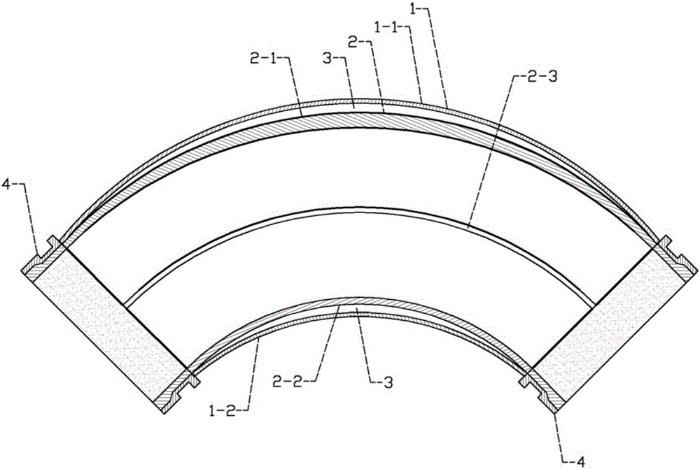
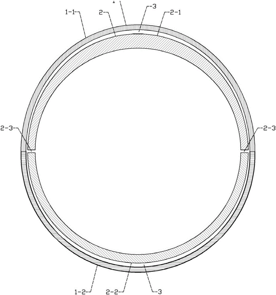
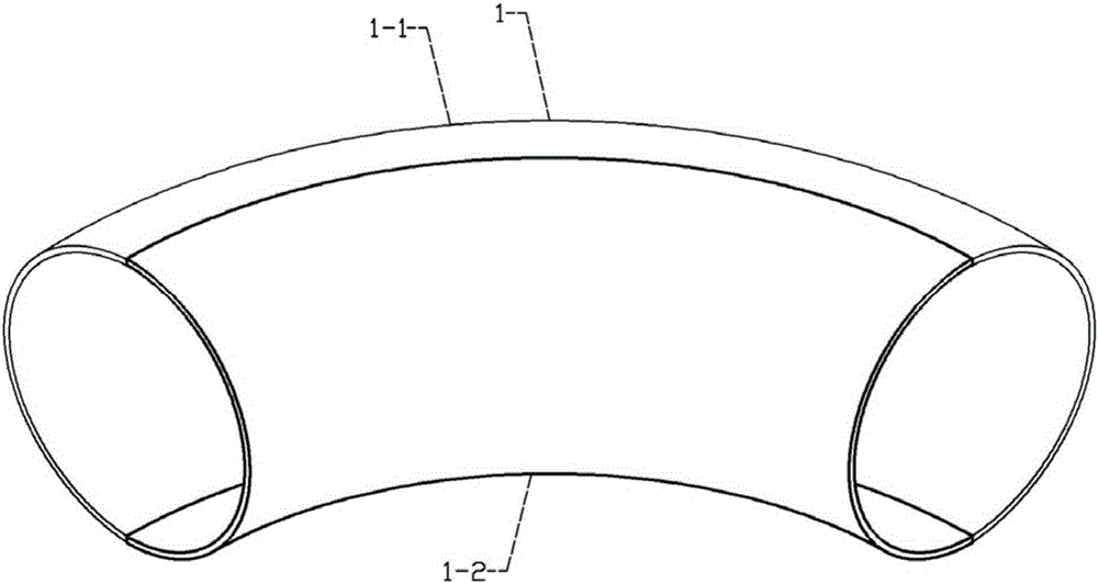
[0047] It can be seen from the content of the invention that a concrete pump truck automatically fills two-layer and two-half wear-resistant elbows and its manufacturing method. Blue 4, and there is a reserved filling reinforcement bin 3 between the outer protective elbow 1 and the inner heterogeneous wear-resistant composite elbow 2; the outer protective elbow 1 is formed by the large outer protective elbow 1-1 It is composed of a small bend outer protection bend 1-2; the inner heterogeneous wear-resistant composite bend 2 is composed of an inner wear-resistant large bend 2-1 and an inner wear-resistant small bend 2-2, and the inner wear-resistant large bend 2-1 and the inner wear-resistant small bend 2-2 are of heterogeneous design and form a closed circular cross section. When the concrete is pumped for the first time, the inner wear-resistant big bend 2-1 and the inner wear-resistant The deformation rate of the small bend 2-2 is different due to the heterogeneous design, s...

Embodiment 2

[0060] It can be seen from the content of the invention that in order to increase the wear resistance of the most easily worn position in the middle of the big bend and reduce the cost of raw materials for the wear-resistant layer, the present invention is equipped with an inner layer heterogeneous wear-resistant composite elbow 2; an inner layer heterogeneous wear-resistant composite The elbow 2 is composed of an inner wear-resistant big bend 2-1 and an inner wear-resistant small bend 2-2; the inner wear-resistant big bend 2-1 is provided with an inner wear-resistant big bend outer surface 2-4, The inner wear-resistant small bend 2-2 is provided with an inner wear-resistant small bend outer surface 2-5; wherein the inner wear-resistant large bend 2-1 is designed to be thickened from the two ends A to the middle B and the two sides C Thickening toward the middle part D ensures high wear resistance at the most wearable position in the middle of the big bend; the inner wear-resis...

Embodiment 3

[0064] It can be seen from the content of the invention that in order to reduce the processing difficulty of the wear-resistant elbow and realize the active self-filling function of the outer protective elbow 1 and the inner heterogeneous wear-resistant combination elbow 2, the active self-filling function of the filling and reinforcement chamber 3 is reserved. There is a filling channel 2-3; the filling channel 2-3 is a reserved seam formed after the installation of the inner layer wear-resistant large bend 2-1 and the inner layer wear-resistant small bend 2-2; since the filling channel 2-3 is provided, then The inner wear-resistant large bend 2-1 is not in direct contact with the inner wear-resistant small bend 2-2, so that the edges of the inner wear-resistant large bend 2-1 and the inner wear-resistant small bend 2-2 do not need to be completely processed. Consistent, reducing the difficulty of processing; the filling channel 2-3 directly communicates with the reserved fill...


PUM


Abstract

An auto-fill two-layer in-half wear resistant elbow of a concrete pump truck is formed by an outer-layer protection elbow, an inner-layer heterogeneous wear resistant combined elbow and a wear resistant connecting flange; a reserved filling space is formed between the outer-layer protection elbow and the inner-layer heterogeneous wear resistant combined elbow. The wear resistant elbow is designed into a unique structure with two layers including a protection layer and a wear resistant layer, and the protection layer protects the wear resistant layer, so that the elbow is prevented from being deformed and even damaged by external force in transportation, installation and use processes, and from being deformed and even damaged by internal material impact; when the wear resistant elbow is used for the first time, concrete grout enters the reserved filling space by a reserved filling seam of the heterogeneous combined elbow, so that the outer-layer protection elbow and the inner-layer heterogeneous wear resistant combined elbow are fixed into a whole, thus the overall weight of the elbow is lightened, and the aims of lowering the cost, saving materials and prolonging the service life are achieved.

Description

Technical field: [0001] The invention relates to a conveying connection elbow structure for conveying materials in a fluid state, in particular to an automatic filling two-layer and two-half wear-resistant elbow for a concrete pump truck and a manufacturing method thereof. Background technique: [0002] The forming technologies of elbows mainly include casting forming, compression molding, etc. They are all formed by casting or hot and cold pressing process by forming molds; no matter what kind of machinery and equipment and pipelines, most of them use bending Tubes are mainly used to transport various materials; the materials of elbows include cast iron, stainless steel, alloy steel, malleable cast iron, carbon steel, non-ferrous metals and plastics; in construction, mining, metallurgy, electric power, petroleum, coal, grain processing, etc. In the industry, materials are conveyed through pipeline pressure, and the conveying pipe is subject to high pressure and severe wear;...

Claims


Application Information

Patent Timeline
IPC IPC(8): F16L43/00F16L57/06
Inventor 周朝辉
Owner 长沙天赋机械设备有限公司
Learn More