
An industrial dust removal device with intelligent control partition

A technology of intelligent control and dust removal device, applied in separation methods, dispersed particle separation, dispersed particle filtration, etc., can solve the problem of incomplete cleaning, and achieve the effect of improving the cleaning effect and avoiding dust.

Active Publication Date: 2021-12-28
山东美蓝环保科技有限公司
View PDF0 Cites 0 Cited by
  • Summary
  • Abstract
  • Description
  • Claims
  • Application Information

AI Technical Summary

Problems solved by technology

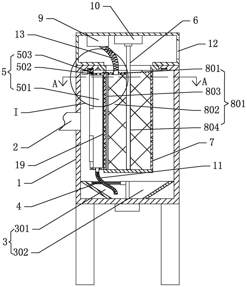
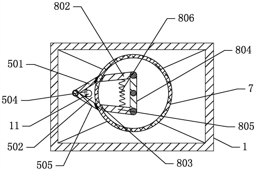
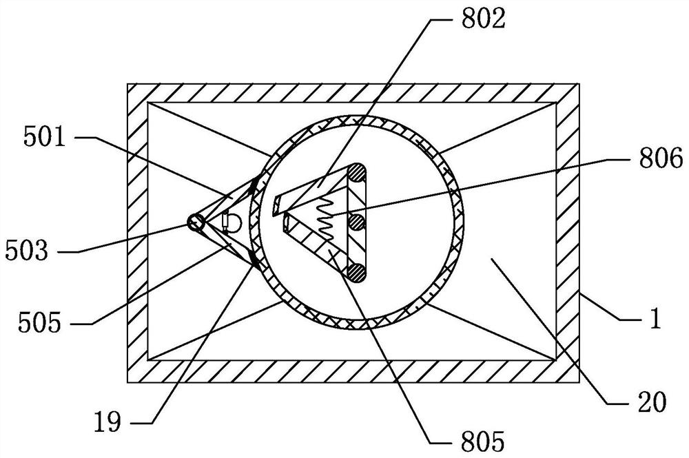
[0003] The purpose of this application is to solve the problem that when the existing filter cartridge is used for back blowing and dust removal, a large amount of dust appears outside the filter cartridge, and when the compressed air in the filter cartridge is reduced, a large part of the dust outside the filter cartridge still remains. Attached to the outside of the filter cartridge, resulting in incomplete dust removal. This application designs an industrial dust removal device with intelligent control partitions. The specific technical solution adopted is:

Method used


Image

  • An industrial dust removal device with intelligent control partition
  • An industrial dust removal device with intelligent control partition
  • An industrial dust removal device with intelligent control partition

Examples


Embodiment Construction

[0039] In order to clearly illustrate the technical features of this solution, the present invention will be described in detail below through specific implementation methods and in conjunction with the accompanying drawings.

[0040] In addition, in the description of the present invention, it should be understood that the terms "center", "upper", "lower", "front", "rear", "left", "right", "vertical", "horizontal" ", "Top", "Bottom", "Inner", "Outer", "Axial", "Radial", "Circumferential" and other indicated orientations or positional relationships are based on the orientations or positional relationships shown in the drawings , is only for the convenience of describing the present invention and simplifying the description, but does not indicate or imply that the referred device or element must have a specific orientation, be constructed and operated in a specific orientation, and thus should not be construed as limiting the present invention.

[0041] Such as Figure 1-6 As ...


PUM


Abstract

The application is an industrial dust removal device with intelligent control partition, which belongs to the field of ring dust collectors, including one end of the inner rotating shaft rotatingly arranged on the casing, and the other end extending into the inside of the filter cartridge; the inner recoil cover is arranged on the inner rotating shaft, and the inner recoil cover Set in the filter cartridge, the edge of the inner recoil cover is in contact with the inner wall of the filter cartridge; the pulse gas source communicates with the recoil area inside the inner recoil cover; The guide rail is set along the circumference of the filter cartridge and concentric with the circular cross-section of the filter cartridge. The edge of the outer dust collection cover is in contact with the outer wall of the filter cartridge. The partially closed dust collection area and the partially closed recoil area correspond to the filter cartridge. The same area; through the above scheme, the part of the filter cartridge corresponding to the recoil cover and dust collection cover can be recoiled and cleaned, and the dust blown out of the filter cartridge will settle in the dust collection cover and fall into a specific ash hopper, avoiding A large amount of dust is generated outside the filter cartridge, thereby improving the dust removal effect of the filter cartridge.

Description

technical field [0001] The invention relates to the field of environmental protection dust collectors, in particular to an industrial dust removal device with intelligent control partitions. Background technique [0002] There are two ways to remove dust in the traditional filter cartridge dust collector, one is high-pressure air flow back blowing, and the other is to disassemble the filter cartridge and regularly clean dust on a specific dust removal device. For the latter, it is always time-consuming and labor-intensive to remove the filter cartridge regularly on a specific dust removal device, and it also involves the process of disassembling the filter cartridge from the dust collector; while the process of high-pressure air blowback is through The compressed air in the air bag enters the inside of the filter cartridge, causing instant positive pressure in the filter cartridge and causing bulging and micro-movement. The dust deposited on the outside of the filter cartrid...

Claims


Application Information

Patent Timeline
Patent Type & Authority Patents(China)
IPC IPC(8): B01D46/00B01D46/24
CPCB01D46/2411
Inventor 侯现亮耿子钧吴锋廖全玲
Owner 山东美蓝环保科技有限公司
Learn More