Reactive Power Control Device

A technology of power control and casing, applied in the direction of reactive power adjustment/elimination/compensation, reactive power compensation, casing with display/control unit, etc. panel damage etc.

Inactive Publication Date: 2021-03-02
北京瑞迈三和科技有限公司
View PDF4 Cites 0 Cited by
  • Summary
  • Abstract
  • Description
  • Claims
  • Application Information

AI Technical Summary

Problems solved by technology

[0004] The purpose of the present invention is to provide a reactive power control device to solve the problem that the corners of the display panel of the existing reactive power control device proposed in the above-mentioned background technology have no protection, and collisions during transportation and placement will cause damage to the display panel and affect the device. problem of use

Method used


Image

  • Reactive Power Control Device
  • Reactive Power Control Device
  • Reactive Power Control Device

Examples


Embodiment Construction

[0046] The following will clearly and completely describe the technical solutions in the embodiments of the present invention with reference to the accompanying drawings in the embodiments of the present invention. Obviously, the described embodiments are only some, not all, embodiments of the present invention. Based on the embodiments of the present invention, all other embodiments obtained by persons of ordinary skill in the art without making creative efforts belong to the protection scope of the present invention.

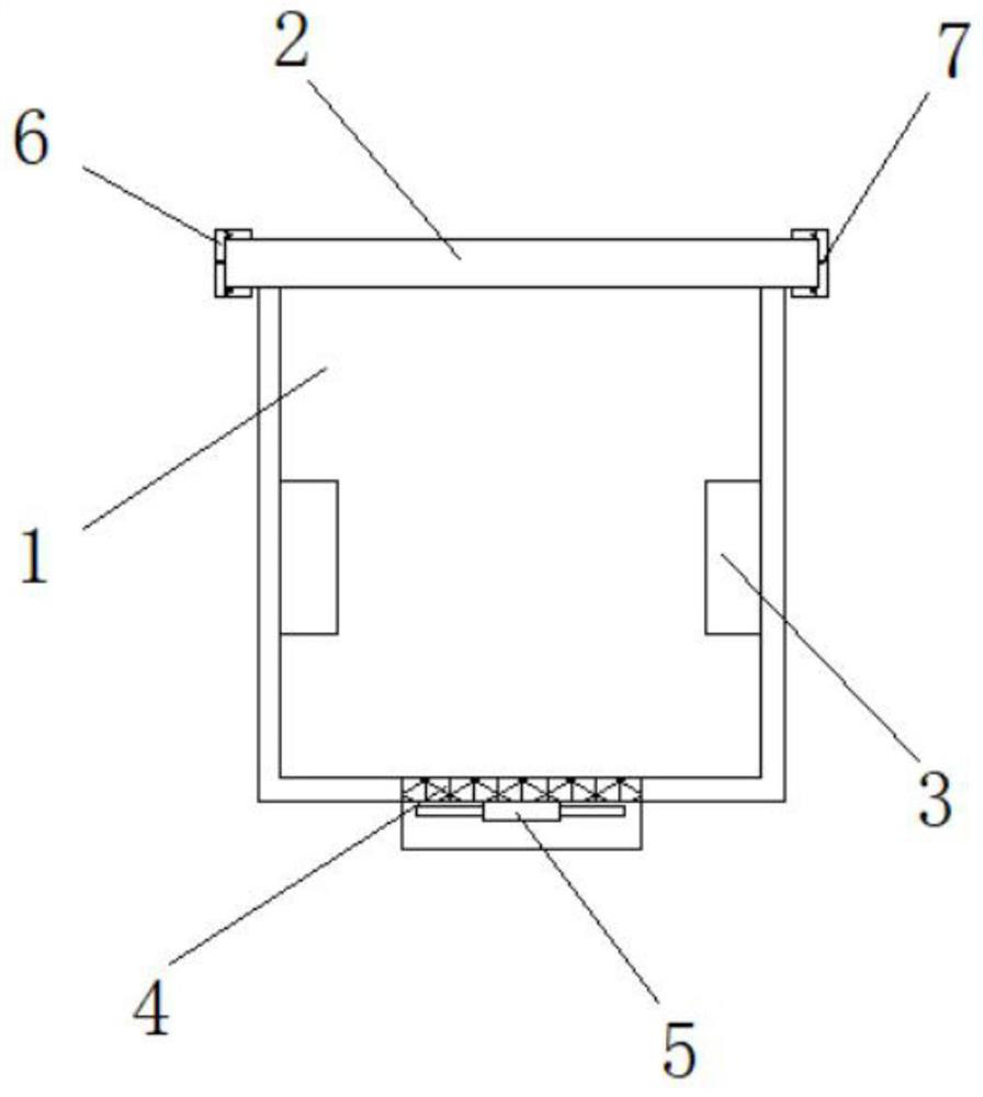
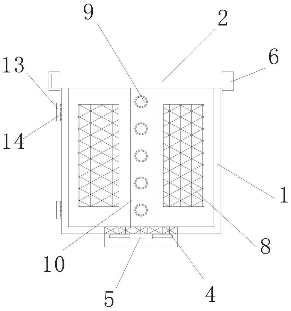
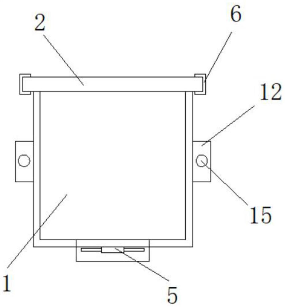
[0047] see Figure 1-4, the present invention provides a technical solution: a reactive power control device, including a housing 1 and a wear-resistant sheet 13, a display panel 2 is provided above the housing 1, and rubber pads 6 are provided at the four corners of the upper surface of the display panel 2 , the inside of the rubber pad 6 is provided with a first spring 7, the rubber pad 6 and the display panel 2 are adhesively connected, and the rubber pad 6...


PUM


Abstract

The invention discloses a reactive power control device, which comprises a display panel arranged above the casing, and rubber pads are arranged at four corners of the upper surface of the display panel, a first spring is arranged inside the rubber pad, and a first spring is arranged inside the casing. Heat-absorbing boxes are arranged on the left and right sides of the interior of the housing, a ventilating mesh is arranged under the interior of the casing, and a fan is arranged under the ventilating mesh, and limiting grooves are arranged on the left and right sides of the exterior of the casing. And the inside of the limiting groove is provided with a limiting screw hole, the inside of the limiting screw hole is provided with a screw, and the outside of the screw is connected with a positioning block, the surface of the positioning block is provided with a positioning hole, and the inside of the limiting groove is provided with a positioning block. Both upper and lower sides are provided with cooling nets, the anti-wear sheet is arranged behind the housing, and a waterproof pad is arranged inside the anti-wear sheet. The reactive power control device is provided with rubber pads at the four corners of the display panel, which can buffer and protect the display panel and prevent the display panel from being damaged due to collision during transportation and placement.

Description

technical field [0001] The invention relates to the technical field of controllers, in particular to a reactive power control device. Background technique [0002] The reactive power control device is the control of reactive power exchange between the converter or HVDC converter station and the AC grid connected to it. They all rely on the establishment of an alternating magnetic field to convert and transfer energy. The electric power required to establish an alternating magnetic field and induced flux is called reactive power. [0003] The corners of the display panel of the existing reactive power control device are not protected, and collisions during transportation and placement will cause damage to the display panel and affect the use of the device. Contents of the invention [0004] The purpose of the present invention is to provide a reactive power control device to solve the problem that the corners of the display panel of the existing reactive power control devi...

Claims


Application Information

Patent Timeline
Patent Type & Authority Patents(China)
IPC IPC(8): H05K5/00H05K5/02H05K7/20H02J3/18B08B7/02B01D46/00B01D46/10
CPCH05K5/0017H05K5/0217H05K5/0213H05K7/20445H05K7/20136H02J3/18B08B7/02B01D46/10B01D46/76Y02E40/30
Inventor 刘凤侠
Owner 北京瑞迈三和科技有限公司
Why Eureka
Try Eureka