Woodworking lathe capable of automatically adjusting position of turning tool tray

A woodworking lathe, automatic adjustment technology, applied to woodworking lathes, wood processing equipment, manufacturing tools, etc., can solve the problems of turning tool tray deflection, inconvenient use, lathe vibration, etc.

Inactive Publication Date: 2021-09-14
李涵宇
View PDF0 Cites 0 Cited by
  • Summary
  • Abstract
  • Description
  • Claims
  • Application Information

AI Technical Summary

Problems solved by technology

[0003] In order to adapt to different processing situations, the turning tool trays on which the turning tools are installed are generally movable and adjustable. When using woodworking lathes in the current market, the corresponding turning tools need to be installed first, and then the tray should be adjusted to a suitable position and When the turning tool is

Method used


Image

  • Woodworking lathe capable of automatically adjusting position of turning tool tray
  • Woodworking lathe capable of automatically adjusting position of turning tool tray
  • Woodworking lathe capable of automatically adjusting position of turning tool tray

Examples


Embodiment 1

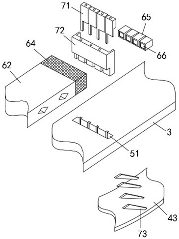
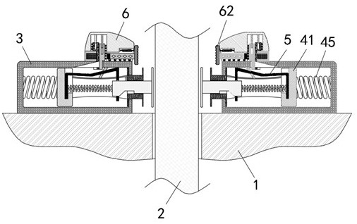
[0030] as attached figure 2 To attach Image 6 Shown:

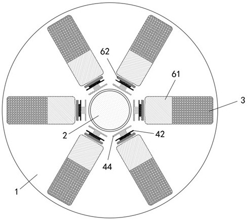
[0031] Including the lathe body 1 and the pallet part 2, the front of the lathe body 1 and the outer side of the pallet part 2 are fixedly installed with evenly distributed fixed seats 3, and the inner part of the fixed seat 3 is equipped with a detection assembly 4, and the detection assembly 4 is installed with elastic Sheet 5, the top of the fixed seat 3 is equipped with a correction assembly 6, the correction assembly 6 includes a support 61, a strike plate 62 and a metal box 65, the strike plate 62 is fixedly connected with a driven magnetic block 64, and the interior of the metal box 65 is fixedly installed There is a driving magnetic block 66, and a metal cover plate 7 is movably installed between the metal box 65 and the driven magnetic block 64.

[0032] Further, the detection assembly 4 includes a slider 41 slidably installed inside the fixed seat 3, and one end of the fixed seat 3 close to the tray part 2 is...

Embodiment 2

[0040] as attached figure 1 To attach Image 6 Shown:

[0041] The present invention provides a woodworking lathe capable of automatically adjusting the position of the turning tool tray, comprising a lathe main body 1 and a pallet part 2, the front of the lathe main body 1 and the outer side of the pallet part 2 are fixedly installed with evenly distributed fixing seats 3, the fixing seats 3 The internal activity of the detection assembly 4 is installed, and the elastic sheet 5 is installed on the detection assembly 4. The correction assembly 6 is installed on the top of the fixed seat 3. The correction assembly 6 includes a support 61, a strike plate 62 and a metal box 65. On the strike plate 62 A driven magnetic block 64 is fixedly connected, a driving magnetic block 66 is fixedly installed inside the metal box 65 , and a metal cover plate 7 is movably installed between the metal box 65 and the driven magnetic block 64 .

[0042] Further, the detection assembly 4 includes...


PUM


Abstract

The invention provides a woodworking lathe capable of automatically adjusting the position of a turning tool tray. The lathe comprises a lathe body and a tray piece, wherein evenly-distributed fixing bases are fixedly installed on the outer side of the tray piece, detection assemblies are movably installed in the fixing bases, elastic pieces are installed on the detection assemblies, and correction assemblies are installed at the tops of the fixing bases; and each correction assembly comprises a support, a collision plate and a metal box, wherein a driven magnetic block is fixedly connected to the collision plate, a driving magnetic block is fixedly installed in the metal box, and a metal cover plate is movably installed between the metal box and the driven magnetic block. When the tray piece deflects, a detection ejection plate is pressed to move inwards, then a sliding block is driven to move, a push plate pushes an inner cover plate to move upwards, the metal box is opened, the elastic pieces bounce upwards into clamping groove, an outer cover plate is pushed to move upwards, a magnetic field of the driving magnetic block is not isolated any more, the driving magnetic block and the driven magnetic block generate the repulsive force of the same magnetism, and the collision plates are pushed to move quickly and collide with the tray piece, so that the tray piece is reset through collision, and the function of automatically adjusting the turning tool tray is achieved.

Description

technical field [0001] The invention belongs to the technical field of woodworking lathe cutterheads, in particular to a woodworking lathe capable of automatically adjusting the position of a turning tool tray. Background technique [0002] Woodworking lathe is a kind of machine that is often used in the processing and production of wood products. It can process cylindrical parts, tapers and threads. Drills, reamers, reamers, taps and knurls can also be used on the lathe Therefore, different types of turning tools are also equipped on woodworking lathes to meet different processing requirements. [0003] In order to adapt to different processing situations, the turning tool trays on which the turning tools are installed are generally movable and adjustable. When using woodworking lathes in the current market, the corresponding turning tools need to be installed first, and then the tray should be adjusted to a suitable position and When the turning tool is in contact with th...

Claims


Application Information

Patent Timeline
IPC IPC(8): B27C7/00B27C7/06
CPCB27C7/00B27C7/06
Inventor 李涵宇
Owner 李涵宇
Why Eureka
Try Eureka