Automatic firearm having an inertial automation system

A technology of automation systems and firearms, applied in the directions of light weapons, weapon accessories, weapon types, etc., can solve the problems of unstable functioning and unreliable automatic devices.

Pending Publication Date: 2021-09-21
V M 波卡利亚耶夫 +1
View PDF9 Cites 0 Cited by
  • Summary
  • Abstract
  • Description
  • Claims
  • Application Information

AI Technical Summary

Problems solved by technology

[0006] The disadvantage of this design is the unreli

Method used


Image

  • Automatic firearm having an inertial automation system

Examples


Embodiment Construction

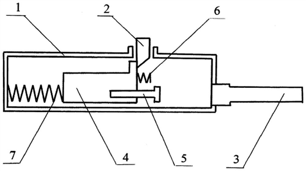
[0012] As an example, the drawings demonstrate a design with a buffer spring between the bolt support and the front wall of the firing mechanism housing and a main spring between the bolt support and the rear wall of the firing mechanism housing.

[0013] The invention is illustrated by the accompanying drawings (see figure 1 ). The firing mechanism housing (pos. 1) includes the magazine latch (pos. 2), the barrel (pos. 3), the bolt support (pos. 4) with the bolt (pos. 5). The buffer spring (pos. 6) is fixed to the bolt support. The main spring (pos. 7) is mounted between the bolt support and the rear wall of the firing mechanism housing. The design works similarly to the above.


PUM


Abstract

The invention relates to mechanisms for cocking an automatic weapon. An automatic firearm having an inertial automation system comprises a breech, a barrel, a bolt support with a bolt, a recoil spring and a return spring, a trigger mechanism, an ammunition supply mechanism and a bolt support latch. The latch fixes the bolt support in a rear position and is controlled with a trigger. A shot is produced at the instant the bolt support arrives in a front position. A mechanism for supplying cartridges to a cartridge chamber makes it possible to load the weapon when the bolt support is fixed in the rear position. Stable operation of an inertial automation system is achieved.

Description

technical field [0001] The present invention is in the field of military equipment, namely automatic (self-loading) firearms [F41C7 / 00, F41C3 / 00, F41A21 / 00]. Background technique [0002] Among the devices currently in existence we know of a self-loading rifle with an inertial automatic, designed by Karl Sjogren (N739,732, patent granted 22 September 1903, O.A.T. SJOGREN, AUTOMATIC GAN, 13 July 1901 application date). [0003] A rifle with an inertial automatic device consisting of a firing mechanism housing, a barrel, a massive bolt support, a buffer spring between the bolt support and the rear wall of the firing mechanism housing , trigger and firing mechanism, ammunition feeding mechanism, buttstock, and aiming equipment. [0004] How the rifle works: [0005] The bolt support is forced rearward, the trigger and firing mechanism are cocked, the main spring is compressed, the bolt support moves forward, the barrel is fed, the bolt moves into position, the trigger is dep...

Claims


Application Information

Patent Timeline
IPC IPC(8): F41C7/00F41A5/02
CPCF41A5/02F41A3/82F41A3/54F41A17/16F41A19/00
Inventor V·M·波卡利亚耶夫S·波卡利亚耶夫
Owner V M 波卡利亚耶夫
Why Eureka
Try Eureka