Lightweight human body power assisting device

A power-assisting and lightweight technology, applied in manipulators, program-controlled manipulators, manufacturing tools, etc., can solve the problems of easy to wear skin, stiff action, user injury, etc., achieve low material strength requirements, improve flexibility, and light structure. Effect

Pending Publication Date: 2021-09-24
极壳科技(上海)有限公司
View PDF2 Cites 0 Cited by
  • Summary
  • Abstract
  • Description
  • Claims
  • Application Information

AI Technical Summary

Problems solved by technology

[0005] In the existing design, as shown above, hinge pins and shafts are often used as ankle joint transmission components, and rigid connections such as transmission arm components and guide rods are used to directly limit the movement of the ankle, making the overall movement of the device stiff, resulting in soles of the feet that can only be controlled by equipment. The ankle joint transmission component is the center of rotation, and it rotates forward and backward. Due to the hard connection set on both sides of the ankle joint transmission component, it directly restricts the foot from tilting left and right, resulting in the inability of the human body to move freely;
[0006] At the same time, the hinge pins and shafts are used as the ankle joint transmission components, which have poor contact with the human ankle, which is easy to wear and tear the skin, causing injury to the user

Method used


Image

  • Lightweight human body power assisting device
  • Lightweight human body power assisting device
  • Lightweight human body power assisting device

Examples


Embodiment Construction

[0036] In order to deepen the understanding of the present invention, the present invention will be further described below in conjunction with the accompanying drawings. This embodiment is only used to explain the present invention, and does not constitute a limitation to the protection scope of the present invention.

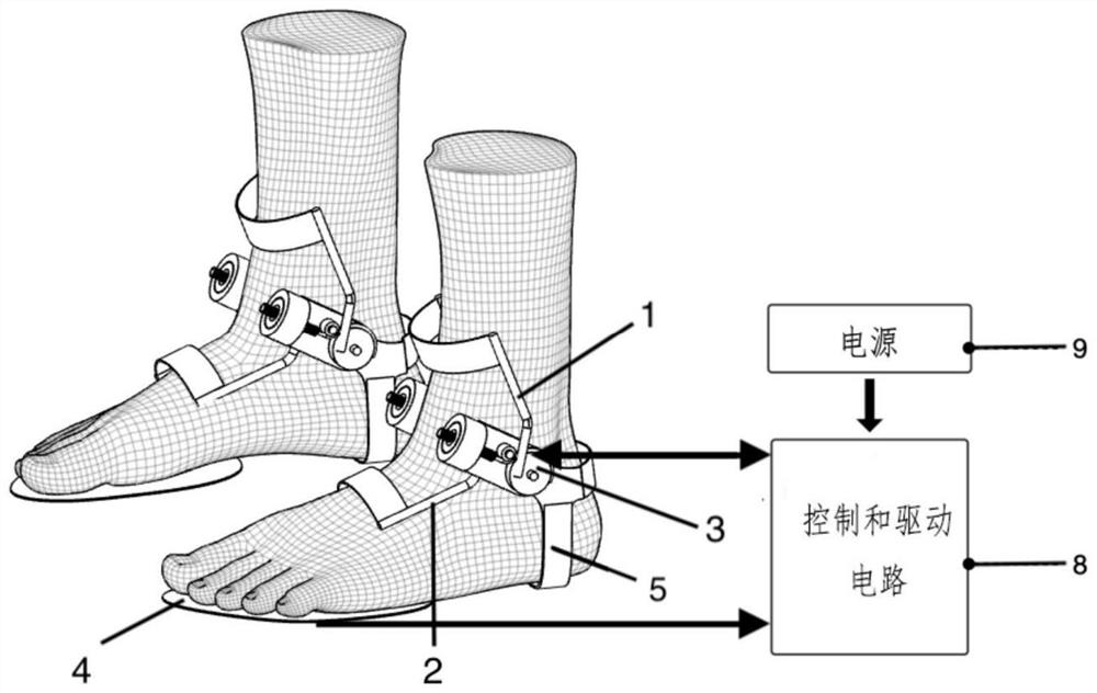
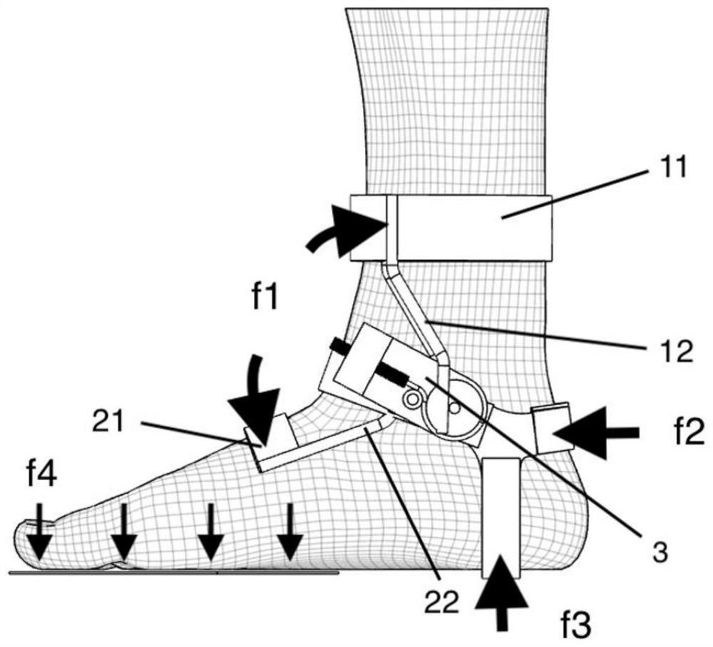
[0037] Such as Figure 1-9 As shown, the light-weight human body assisting device proposed by the present invention includes a first support belt 11, which is a flexible structure, connected to the upper end of the first support arm 12 of the first support mechanism 1, and closely attached to the calf, for supporting the first support The moment transmitted by the arm 12 is transmitted to the lower leg. Its length can be adjusted to suit different body sizes.

[0038] The first support arms 12 , one on each side of each lower leg, are connected to the output structure driving the actuator 3 and the first support belt 11 . It is used to transmit the torque ou...


PUM


Abstract

The invention relates to a lightweight human body power assisting device. The lightweight human body power assisting device comprises a first supporting mechanism arranged on one side of the ankle joint of a human body, a second supporting mechanism arranged on the other side of the ankle joint and a driving actuator which is arranged at the ankle joint of the human body and matched with the biological characteristics of the ankle joint of the human body; the driving actuator is fixed at the ankle of the human body; the first supporting mechanism is arranged at the shank of the human body, and the second supporting mechanism is arranged at the sole of the human body; and the driving actuator can drive the second supporting mechanism to drive the sole to rotate around the ankle, so that the sole swings relative to the shank. The driving actuator is arranged at the ankle joint, and force is applied to the ankle joint and transmitted to the two sides of the ankle joint through the first supporting mechanism and the second supporting mechanism, so that the relative swing of the limb on one side of the ankle joint relative to the limb on the other side of the ankle joint is realized, the device takes the ankle joint of the organism as a rotating point, auxiliary force application is realized, and compared with an existing mechanical exoskeleton, the device is more matched with the use and operation of a human body.

Description

technical field [0001] The invention belongs to the field of human body exoskeleton assisting, in particular to a lightweight human body assisting device. Background technique [0002] The human body's booster device, also known as an exoskeleton, is mainly used to enhance the physical fitness of the human body, reduce exercise metabolism, improve exercise capacity, or in the field of medical rehabilitation, enabling the disabled and the elderly to regain exercise ability. The power-assisted device applied to the human body is still in the early stage from the perspective of development, subject to sensor technology, drive technology, control technology, actuator power density and other issues, the classic power-assisted device has a large structure design, heavy mass, high cost, and stiff action The boosting effect is limited, and it is often partial labor saving and overall labor. It is only in the stage of conceptual products or scientific research, and has not yet appear...

Claims


Application Information

Patent Timeline
Patent Type & Authority Applications(China)
IPC IPC(8): B25J9/00
CPCB25J9/0006
Inventor 孙宽
Owner 极壳科技(上海)有限公司
Why Eureka
Try Eureka