Heat flow characteristic testing device and method for bearing for drive axle
A technology of characteristic test and drive device, which is used in measurement devices, material inspection products, instruments, etc., can solve the problem that the lubrication conditions and working conditions cannot reach the internal working conditions of the drive axle, there is no internal heat flow characteristic test of the bearing, and there is no bearing installation, etc. question
- Summary
- Abstract
- Description
- Claims
- Application Information
AI Technical Summary
Problems solved by technology
Method used
Image
Examples
Embodiment 1
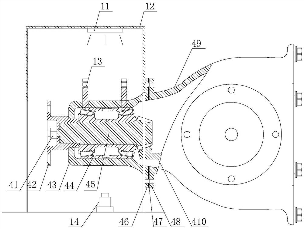
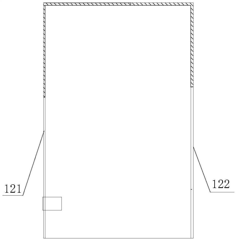
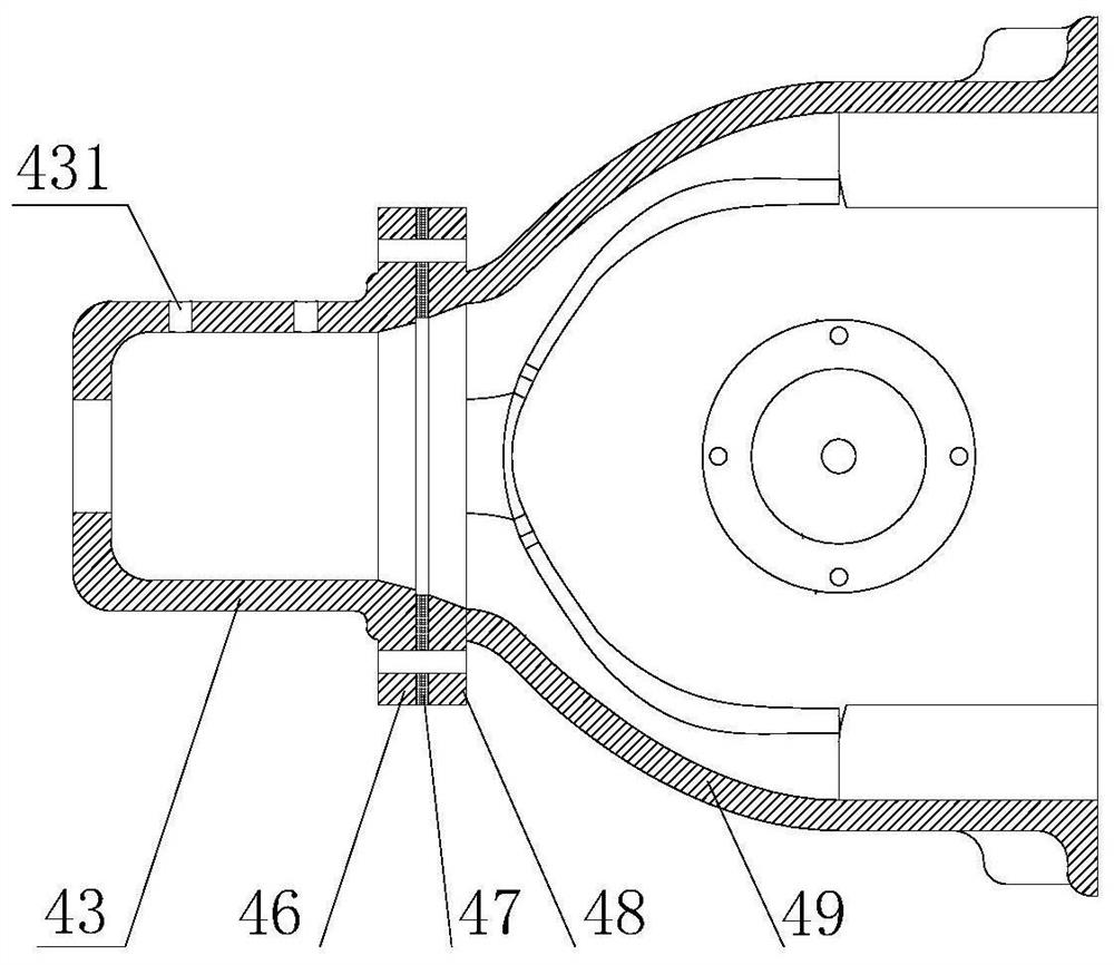
[0049] Bearing heat flow characteristic test device for drive axle, including base 3, final reducer 4, driving device 2 and test device 1 installed on final reducer 4, final reducer 4 and driving device 2 are fixed on the base by bolts 3, the driving device 2 is connected to the final reducer 4 through the test device 1, and the test device 1 includes a temperature sensor 13 and a high-speed camera 14. combine image 3 , in order to visually photograph and observe the flow state of the lubricating oil flowing through the double-row tapered roller bearing 44, the housing of the final reducer 4 needs to be made into two parts: the housing of the final reducer 4 includes an auxiliary housing 49 and a transparent material Observation housing 43 made, observation housing 43 is fixedly connected with auxiliary housing 49, double-row tapered roller bearing 44 is installed in observation housing 43, and temperature sensor 13 is installed on the side wall of observation housing 43 and ...
Embodiment 2
[0060] Embodiment 2 is basically the same as Embodiment 1. The difference is that a fixed frame 5 for fixing the main reducer 4 is installed on the base 3. The fixed frame 5 keeps the final drive 4 in a stable state during operation. The fixed frame 5 Set at the center position of base 3. A side plate 51 is installed on the side of the fixed frame 5, and the first fastening bolt connected with the side of the main reducer 4 is installed on the side plate 51. The second fastening bolt 53 connected to the top of the gearbox 4, the left and right sides of the fixed frame 5 are also equipped with an adjustment base plate 56 for supporting the connecting flange of the final reducer 4, and the fixed frame 5 includes a number of uprights 54 and beams 55 , the quantity of column 54 and crossbeam 55 of present embodiment is all four, and the bottom of column 54 is fixed on the base platform 3 by bolt, is provided with threaded hole above column 54, and threaded hole facilitates crossbe...
Embodiment 3
[0062] A kind of testing method that adopts the test device for heat flow characteristic of drive axle bearing in embodiment 1 or 2, comprises the steps:
[0063] Step a, adding lubricating oil with a tracer factor in the observation housing 43 of the main reducer 4, the tracer factor is preferably phosphor powder, which is convenient for the high-speed camera 14 to observe;
[0064] Step b, turn on the lighting lamp 11 in the shading box 12; the lighting lamp 11 illuminates and observes the inside of the casing 43, which is convenient for the high-speed camera 14 to take pictures;
[0065] Step c, start the driving device 2 and the loading device 6, mode working environment, the loading device 6 constantly changes the loading load;
[0066] Step d, start the test device, the high-speed camera 14 tracks the motion characteristics of the tracer in the final reducer 4, and the temperature sensor 13 tests the temperature characteristics of the double-row tapered roller bearing 44...
PUM
 Abstract
Description
Claims
Application Information
 - R&D
- Intellectual Property
- Life Sciences
- Materials
- Tech Scout
- Unparalleled Data Quality
- Higher Quality Content
- 60% Fewer Hallucinations
Browse by: Latest US Patents, China's latest patents, Technical Efficacy Thesaurus, Application Domain, Technology Topic, Popular Technical Reports.
© 2025 PatSnap. All rights reserved.Legal|Privacy policy|Modern Slavery Act Transparency Statement|Sitemap|About US| Contact US: help@patsnap.com


