Test probe, test probe module and test device

A technology for testing probes and needle valves, applied in the field of integrated circuit testing, to achieve the effect of saving the budget for mechanical rigidity

Active Publication Date: 2021-10-01
绅克半导体科技(苏州)有限公司
View PDF8 Cites 0 Cited by
  • Summary
  • Abstract
  • Description
  • Claims
  • Application Information

AI Technical Summary

Problems solved by technology

[0004] The technical problem to be solved by the present invention is to overcome the deficiencies in the prior art, and provide a method that utilizes the lateral pressure of the head to make the head fully contact with the inner wall of the metallized through hole, so as to ensure good electrical conduction and avoid the problem caused by the number of probes. Increased test probes, test probe modules and test devices that cause the contact surface of the carrier board or test probe module to be easily deformed and warped, resulting in poor contact

Method used


Image

  • Test probe, test probe module and test device
  • Test probe, test probe module and test device
  • Test probe, test probe module and test device

Examples


Embodiment 1

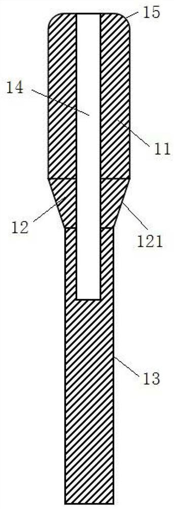
[0046] This embodiment provides a test probe 10 for contacting each alignment contact 31 on the carrier board 30 , wherein the alignment contact 31 may be a metallized through hole. The test probe 10 comprises a head 11 , a transition 12 and a tail 13 , wherein the head 11 and the tail 13 form the main body of the test probe, and the transition 12 is arranged between the head 11 and the tail 13 .

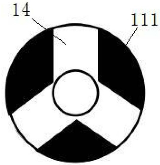
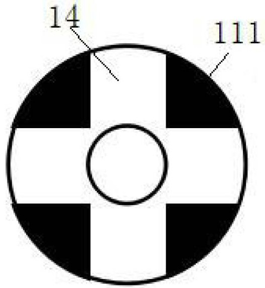
[0047] see figure 1 As shown, the above-mentioned head 11 includes at least two needle flaps 111 that can be opened or closed. The area surrounded by the needle flaps 111 in the opened state has a first area, and the area surrounded by the needle flaps 111 in the closed state has The second area, and the first area is larger than the inner hole area of ​​the metallized through hole, and the second area is smaller than the inner hole area of ​​the metallized through hole. In a natural state, at least two needle petals 111 are in an open state.

[0048]Above-mentioned transition part...

Embodiment 2

[0057] see Figure 5 and Image 6 As shown, this embodiment provides a test probe module, on which the probe array is used to contact the alignment contacts 31 on the carrier board 30 , wherein the alignment contacts 31 may be metallized through holes. The test probe module includes a probe array, a pinhole set and ejector pins 24 .

[0058] The above-mentioned probe array includes at least two test probes 10 as in the first embodiment. The specific structure of the test probes 10 has been described in detail in the first embodiment, and will not be repeated here in this embodiment.

[0059] The above-mentioned pinhole kit includes a movable plate 21, a fixed plate 22 and an extruded part 23. The movable plate 21 includes a first through hole 211 capable of accommodating the test probe 10 moving therein, and the inner side wall of the first through hole 211 is provided with The extruding part 23 that cooperates with the inclined surface 121 on the transition part 12 of the t...

Embodiment 3

[0070] An embodiment of the present invention provides a test device, including a test machine and a test probe module as in Embodiment 2, where the test probe module is assembled on the test machine.


PUM


Abstract

The present invention relates to a test probe comprising: a head comprising at least two needle flaps that can be opened or closed; a tail part which forms a main body of the test probe; and a transition part which comprises two ends, wherein one end is connected with the head part, the other end is connected with the tail part, and the transverse size of the end connected with the head part is larger than that of the end connected with the tail part, so that the outer wall of the transition part is provided with an inclined surface shrinking from the head part to the tail part; when the extrusion piece moves from the tail part to the head part along the inclined surface, the transition part is subjected to extrusion force to drive the at least two needle flaps to be closed, so that the closed head part can enter the metalized through hole in the carrier plate; and when the extrusion force is removed, the at least two needle petals expand naturally so as to abut against the inner wall of the metalized through hole in the carrier plate. Therefore, the problem of poor contact caused by easy deformation and warping of the contact surface of the carrier plate or the test probe module due to increase of the number of the probes can be avoided, and the budget of mechanical rigidity of an installation mechanism is omitted.

Description

technical field [0001] The invention relates to the technical field of integrated circuit testing, in particular to a test probe, a test probe module and a test device. Background technique [0002] Integrated circuit automatic test machines usually use pogo pins to connect to the carrier board of the circuit under test. The pogo pin plate is composed of multiple spring probe modules, and each spring probe on each spring probe module is responsible for the connection of a test signal. When the test machine is connected to the carrier board, the spring probes of the test machine should touch the corresponding contacts on the carrier board, and a certain pressure should be formed so that each spring probe is effectively compressed to ensure Reliable electrical conduction. In a typical application scenario, when the spring probe is compressed by 1mm~2mm, the elastic force generated by it is 50g~200g. For a test machine with 1000 needles, there will be at least 50kg of pressu...

Claims


Application Information

Patent Timeline
IPC IPC(8): G01R1/067G01R1/073G01R31/28
CPCG01R1/06711G01R1/07307G01R31/2886
Inventor 魏津胡雪原徐润生
Owner 绅克半导体科技(苏州)有限公司
Why Eureka
Try Eureka