
Eureka
For R&D, Eureka makes reading and utilizing patents & technical documents easy.
Eureka AIR
Designed for self-driven R&D workflows. Generate viable solutions, solve complex R&D challenges, empower your innovation with AI.

Eureka Materials
Designed for material experts only. Revolutionize your material R&D, from search, analyze, to developing new materials.

TechResearch
Generate reliable direction feasibility study reports for your R&D in just a few steps.

TechSeek
Discover and master advanced knowledge NOW. Basics, ideas, possibilities, all at once.

TechMind
As an expert in R&D Theories, TechMind can generates customized viable solutions instantly.

TechRisk
Analyze your overall solution with one click, know your potential R&D risks in advance.

TechMonitor
Get weekly tech updates, stay abreast of the latest tech innovations and key insights.
Home theater three-dimensional placing device
A technology for displaying devices and theaters, applied to projection devices, optics, instruments, etc., can solve problems such as inconvenient cleaning, no protective cover, easy to accumulate dust, etc., and achieve the effect of convenient projection
- Summary
- Abstract
- Description
- Claims
- Application Information
AI Technical Summary
Problems solved by technology
Method used
Image

Examples
Embodiment 1
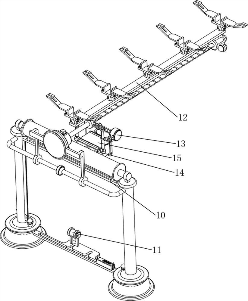
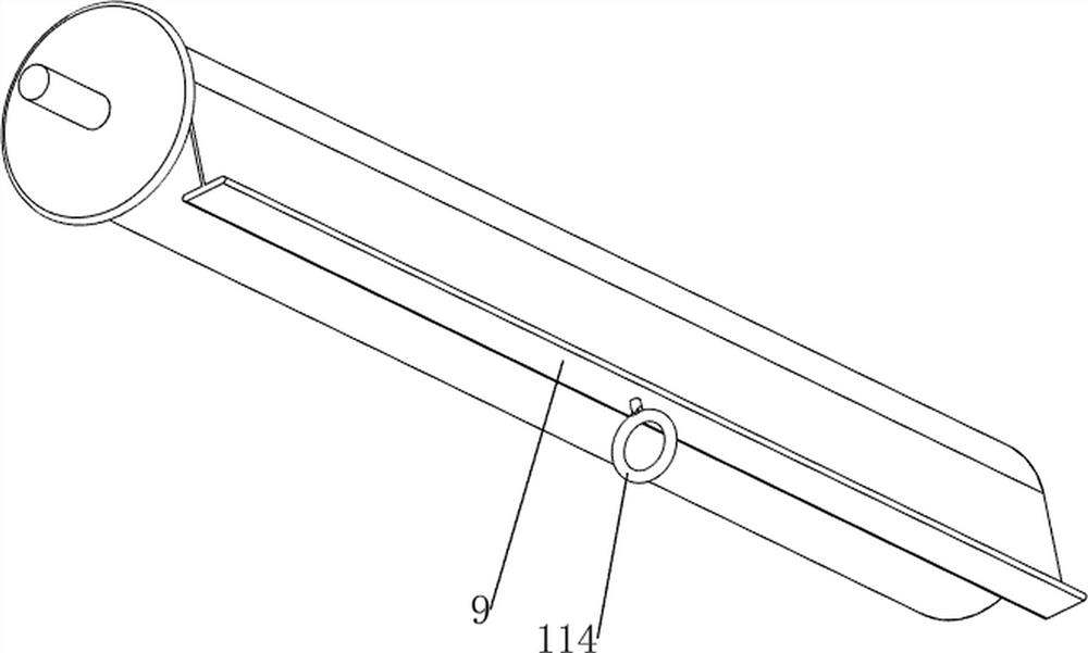
[0036] A home theater stereoscopic display device, such as Figure 1-8 As shown, it includes a first support column 1, a first pallet 2, a second support column 4, a first connecting rod 5, a first fixed column 6, a rotating shaft 7, a curtain 8, a gravity plate 9, a lifting mechanism 10 and a fixed Mechanism 11, the first support column 1 is provided on the left side of the first pallet 2, the second support column 4 is provided on the right side of the first pallet 2, the front upper side of the first support column 1 and the second support column 4 are connected There is a first connecting rod 5, a first fixed column 6 is arranged on the top of the first support column 1 and the second support column 4, and a rotating shaft 7 is arranged between the first fixed columns 6, and a curtain 8 is wound around the rotating shaft 7, A gravity plate 9 is provided on the curtain 8 , a lifting mechanism 10 is provided on the first support column 1 , and a fixing mechanism 11 is connec...
Embodiment 2
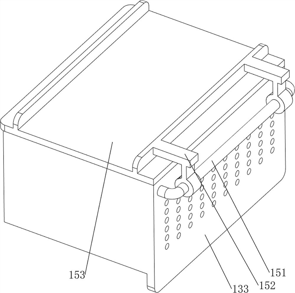
[0041] On the basis of Example 1, such as figure 1 , figure 2 , Figure 9 , Figure 10 , Figure 11 , Figure 12 , Figure 13 , Figure 14 , Figure 15 , Figure 16 with Figure 17 As shown, a transposition mechanism 12 is also included, and the transposition mechanism 12 includes a first fixed frame 121, a second reduction motor 122, a second screw rod 123, a slider 124, a mounting plate 125, a slide rail 126, a fourth fixed The column 127 and the second pressure sensor 128, the first fixed frame 121 is arranged in the middle of the first connecting rod 5, the second geared motor 122 is arranged on the rear side of the first fixed frame 121 through bolts, and the output shaft of the second geared motor 122 passes through The shaft coupling is connected with a second screw rod 123, the second screw rod 123 is threadedly provided with a slider 124, the rear side of the second screw rod 123 is rotated to be provided with a fourth fixed column 127, and the top of the fo...
PUM
 Abstract
Description
Claims
Application Information
 - R&D Engineer
- R&D Manager
- IP Professional
- Industry Leading Data Capabilities
- Powerful AI technology
- Patent DNA Extraction
Browse by: Latest US Patents, China's latest patents, Technical Efficacy Thesaurus, Application Domain, Technology Topic, Popular Technical Reports.
© 2024 PatSnap. All rights reserved.Legal|Privacy policy|Modern Slavery Act Transparency Statement|Sitemap|About US| Contact US: help@patsnap.com