Punching device for binding financial data
A punching device and data technology, applied in the field of financial data management, can solve problems such as inability to keep data neat, data punched, and inability to punch data
- Summary
- Abstract
- Description
- Claims
- Application Information
AI Technical Summary
Problems solved by technology
Method used
Image
Examples
Embodiment 1
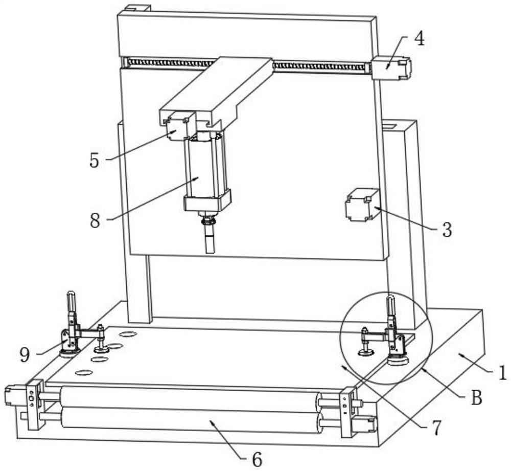
[0057] Such as Figure 1-8 As shown, a punching device for financial data binding according to an embodiment of the present invention consists of a lifting device 3, a lateral moving device 4, a longitudinal moving device 5, a punching mechanism 8, a support seat 1, a paper feeding device 6, and a cover plate 7 and base 9 form.
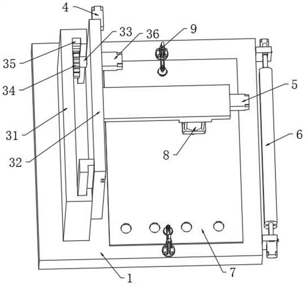
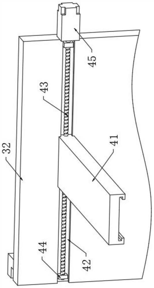
[0058] Among them, when the thickness of the material is too thick or too thin, in order to adjust the punching depth of the material so that it will not cause the problem of insufficient punching depth or hitting the table, a lifting device 3 is provided. The lifting device 3 includes a fixed plate 31, the fixed plate 31 is provided with a movable plate 32, and one end of the movable plate 32 is connected with the limit sliding between the fixed plate 31. By adjusting the height of the movable plate 32 on the fixed plate 31, the depth of the punching Adjustment, the other end of the movable plate 32 is movably connected with a gear 34 through the ro...
Embodiment 2
[0071] On the basis of Example 1, please refer to figure 2 , the gear slot 35 is longitudinally arranged on the fixed plate 31, the gear 34 is located on one side of the gear slot 35, and the gear 34 and the gear slot 35 are meshed and connected.
[0072]By adopting the above technical solution, by fixing the position of the gear groove 35 , when the gear 34 meshes with the gear groove 35 , the gear 34 will move along the direction of the gear groove 35 .
Embodiment 3
[0074] On the basis of Example 1, please refer to Figure 6 , the adjustment device 66 includes a movable rotating shaft 661, the upper support rod 63 is located inside the movable rotating shaft 661 and is connected with the movable rotating shaft 661, and the support frame 65 is located at the position corresponding to the movable rotating shaft 661 to open a limit groove 662, and the supporting frame 65 Bolt holes 663 are opened on both sides of the two sides, and the bolt holes 663 penetrate to the inside of the limiting groove 662, and the bolt holes 663 are connected with fixing bolts 664 through threads.
[0075] By adopting the above-mentioned technical scheme, the distance between the upper roller 61 and the lower roller 62 can be adjusted through the adjustment device 66, so that papers of different widths can be placed, and the upper pole 63 can be adjusted through the movable shaft 661. Limiting support, the position of the movable rotating shaft 661 can be adjuste...
PUM
 Abstract
Description
Claims
Application Information
 - R&D
- Intellectual Property
- Life Sciences
- Materials
- Tech Scout
- Unparalleled Data Quality
- Higher Quality Content
- 60% Fewer Hallucinations
Browse by: Latest US Patents, China's latest patents, Technical Efficacy Thesaurus, Application Domain, Technology Topic, Popular Technical Reports.
© 2025 PatSnap. All rights reserved.Legal|Privacy policy|Modern Slavery Act Transparency Statement|Sitemap|About US| Contact US: help@patsnap.com


