Construction method of side wall of underground structure

A technology of underground structure and construction method, which is applied in the direction of walls, building components, building structures, etc., can solve the time-consuming and labor-intensive problems of cast-in-place side walls, and achieve the effects of improving construction efficiency, shortening construction time, and saving manpower and material resources

Pending Publication Date: 2021-10-12
SHANGHAI TUNNEL ENG CO LTD
View PDF10 Cites 1 Cited by
  • Summary
  • Abstract
  • Description
  • Claims
  • Application Information

AI Technical Summary

Benefits of technology

This new design allows for easier assembly by creating an indoor space with walls without requiring expensive materials or laborious work. It also simplifies the process of constructing buildings from existing structures while still maintain their strength and durability over longer periods of use compared to traditional methods like casting them outdoors.

Problems solved by technology

This technical problem addressed in this patents relates to improving the efficiency and accuracy during building up of under ground structure's sides with casting-on-site methods due to their low speeds compared to other ways like lining or adding forms for better stability. Additionally, there may be issues related to controlling the thickness of cement used on top of these constructions without affecting its effectiveness over longer periods of use.

Method used


Image

  • Construction method of side wall of underground structure
  • Construction method of side wall of underground structure
  • Construction method of side wall of underground structure

Examples


Embodiment approach

[0036] As a preferred embodiment of the present invention, it also includes:

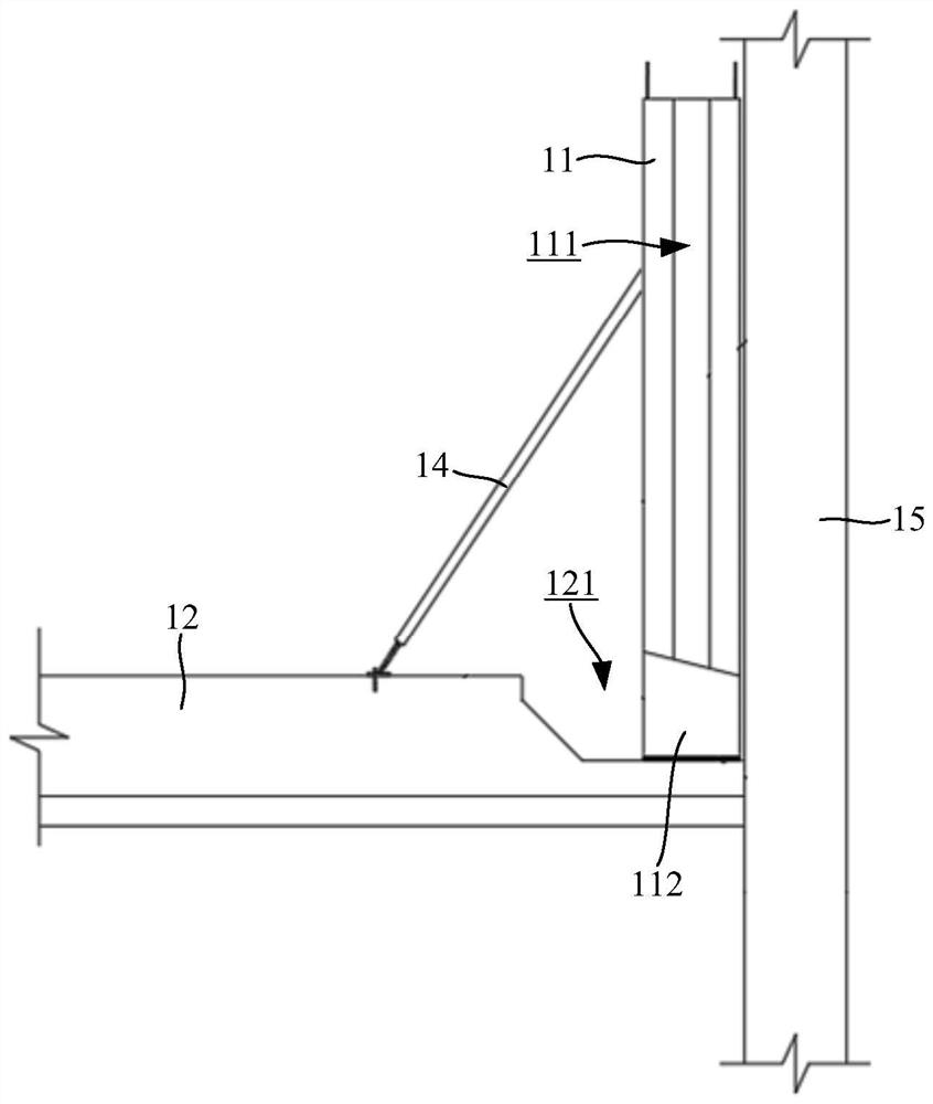
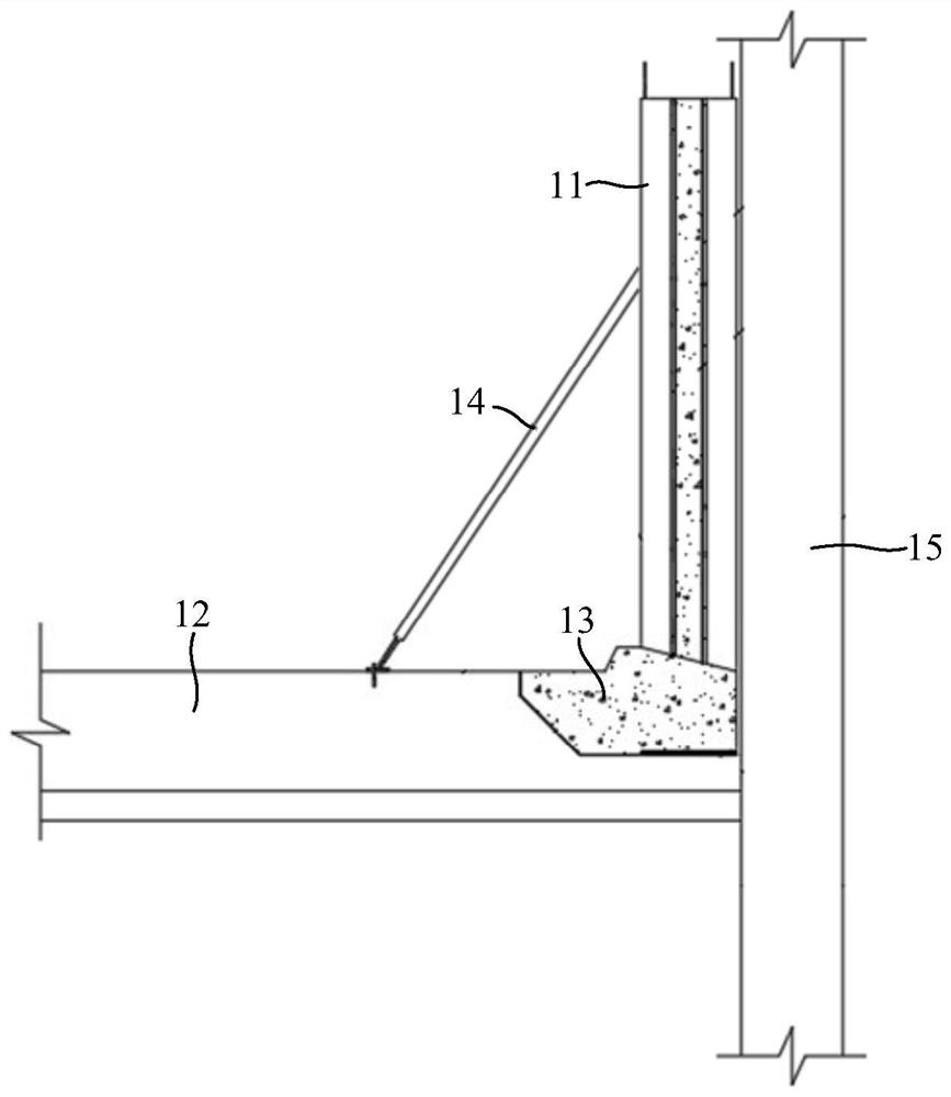
[0037] The diagonal brace 14 is provided, and the diagonal brace 14 is obliquely connected between the prefabricated wall panel 11 and the bottom plate 12 to support and fix the prefabricated wall panel 11. After pouring to form the post-cast structure 13, the diagonal brace 14 is removed.

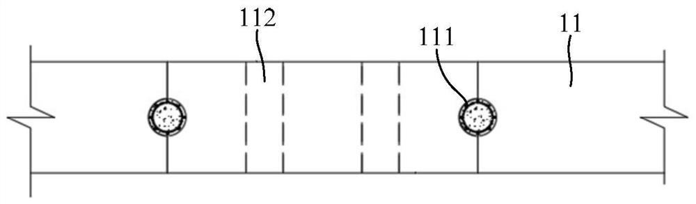
[0038] Further, the bottom of the prefabricated wall panel 11 is provided with several supporting feet 112 at intervals;

[0039] The supporting feet 112 are placed on the bottom surface of the groove 121 , and the supporting feet 112 are buried in the post-casting structure 13 after pouring to form the post-casting structure 13 .

[0040] Specifically, the bottom plate 12 is embedded with bottom plate steel bars, and the part of the bottom plate steel bar corresponding to the groove 121 is exposed outwards, and the bottom of the prefabricated wallboard 11 is pre-embedded with fixing ribs, and the fixing ribs ar...

specific Embodiment approach

[0047] The base plate 12 is formed by pouring at the bottom of the underground structure, and the position of the base plate 12 close to the enclosure structure 15 is depressed downward to form an L-shaped groove 121;

[0048] The prefabricated wallboard 11 is placed close to the enclosure structure 15, and the supporting feet 112 of the prefabricated wallboard 11 are placed on the bottom surface of the groove 121. Since the bottom surface of the groove 121 has a certain slope, some of the supporting feet 112 and the groove 121 There is a gap between the bottom surfaces, and steel plates are filled in the gap;

[0049] Pass the bottom plate steel bars on the upper floor through the support feet 112, bend the bottom plate steel bars on the lower floor upwards and connect them with the fixing bars at the bottom of the prefabricated wall panels 11, and then pour concrete into the grooves 121 to form the post-cast structure 13 , the top surface of the post-cast structure 13 is flu...


PUM


Abstract

The invention discloses a construction method of the side wall of an underground structure. The construction method of the side wall of the underground structure comprises the steps that a bottom plate is formed at the bottom of an underground structure in a pouring mode, and the positions, close to enclosure structures, of the bottom plate are sunken downwards to form grooves; prefabricated wallboards are provided, and the prefabricated wallboards are attached to the corresponding enclosure structures and arranged on the bottom faces of the grooves; and concrete is poured into the grooves to form a post-pouring structure with the top face flush with the top face of the bottom plate, so that the prefabricated wallboards and the bottom plate are fixedly connected. According to the construction method of the side wall of the underground structure, the problem that cast-in-place side walls waste time and labor is effectively solved, a prefabricated wall body is directly mounted on the basement bottom plate, cast-in-place is not needed, the construction efficiency is greatly improved, the construction time is shortened, manpower and material resources are saved, and the construction quality can be guaranteed.

Description


Claims


Application Information

Patent Timeline
Owner SHANGHAI TUNNEL ENG CO LTD
Why Eureka
Try Eureka