Wind tunnel test device based on sonic boom test technology

A test technology and wind tunnel test technology, applied in the field of wind tunnel test devices based on sonic boom test technology, can solve the problems of no reliable test platform, reliability to be verified, and little research on sonic boom, etc., and achieve good practicality. Effects of Sex and Promotional Value

Active Publication Date: 2021-10-15
INST OF HIGH SPEED AERODYNAMICS OF CHINA AERODYNAMICS RES & DEV CENT
View PDF13 Cites 0 Cited by
  • Summary
  • Abstract
  • Description
  • Claims
  • Application Information

AI Technical Summary

Problems solved by technology

The development of sonic boom wind tunnel test technology for more than 60 years is the arduous process of gradually overcoming the above technical problems. After years of research and testing abroad, rich experience has been accumulated, and single-point measurement, multi-point measurement and large-scale measurement of sonic boom signals have been developed. The three-generation test technology for scale measurement has the traditional sonic boom and subwoofer wind tunnel test technology; however, domestic research on sonic boom is not much, and the research work is not systematic, and mainly focuses on the prediction and conceptual design of sonic boom signals On the other hand, the depth and breadth of research on the design and testing of subwoofers are far from enough
Especially for the low-boom design of supersonic aircraft, there are almost no considerations about weight, balance, and low-speed take-off, and there is even a lack of flight verification, so the reliability of the design needs to be verified; The tests are all in the stage of exploration and research, and a reliable test platform has not yet been formed

Method used


Image

  • Wind tunnel test device based on sonic boom test technology
  • Wind tunnel test device based on sonic boom test technology
  • Wind tunnel test device based on sonic boom test technology

Examples


Embodiment Construction

[0030] All features disclosed in this specification, or steps in all methods or processes disclosed, may be combined in any manner, except for mutually exclusive features and / or steps.

[0031] Any feature disclosed in this specification (including any appended claims, abstract and drawings), unless expressly stated otherwise, may be replaced by alternative features which are equivalent or serve a similar purpose. That is, unless expressly stated otherwise, each feature is one example only of a series of equivalent or similar features.

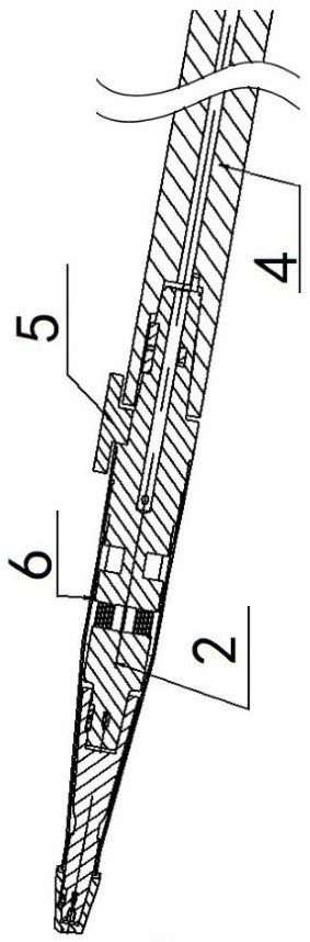
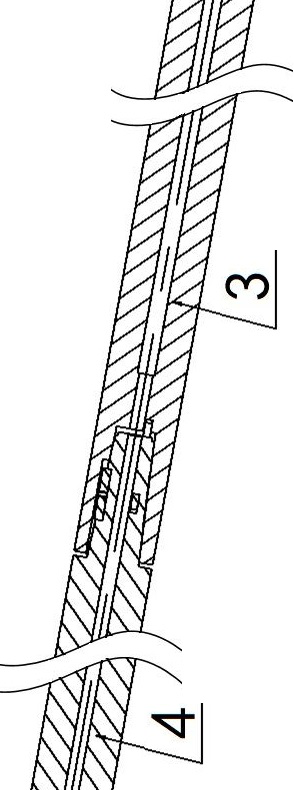
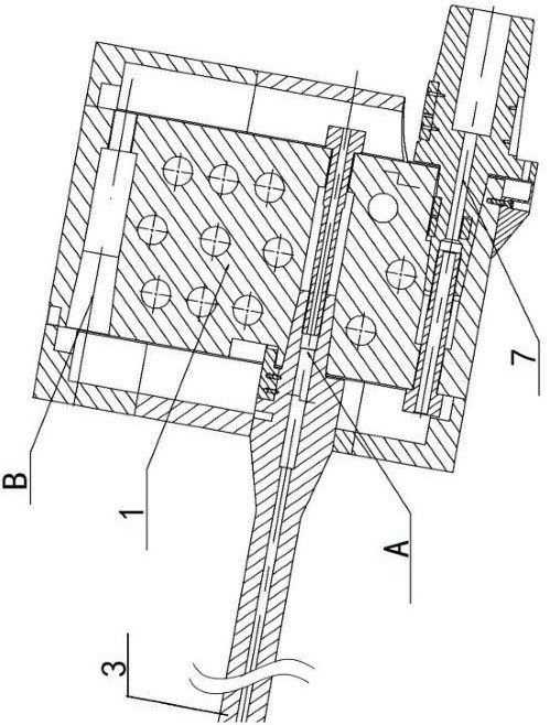
[0032] Such as Figure 1a , Figure 1b , Figure 1c As shown, it is a schematic diagram of the overall structure of this embodiment. Its core components are composed of three parts: an external balance, a test model and a support device. After the above three parts are combined, the wind tunnel of the test model in different angles of attack and relative positions Test; its design load: normal force Y component is 1000N; pitching moment Mz ...


PUM


Abstract

The invention discloses a wind tunnel test device based on a sonic boom test technology. The device comprises an external balance, a test participating model, a supporting device, and an attack angle support used for connecting the supporting device, wherein the external balance is a nested structure, the device comprises a front-end torque element adopting a single-column cantilever rectangular beam structure and a rear-end torque element adopting two groups of mutually vertical multi-column rectangular beam element structures, and the supporting device comprises a position adjusting device, a supporting rod connected to the position adjusting device, and a switching supporting rod coaxially connected with an end part of the supporting rod, the other end of the switching supporting rod is connected with an external balance, and the external balance is connected with a tested model; the external balance exceeds the force and moment load ratio range of a traditional balance, the structure of the external balance breaks through the supporting mode that a traditional internal balance and a single supporting mechanism are adopted for testing, the external balance is applied to a wind tunnel test for achieving the sonic boom test technology for the first time, and the external balance has good practicability and popularization value.

Description

technical field [0001] The invention relates to the field of wind tunnel tests, in particular to a wind tunnel test device based on sonic boom test technology, which is suitable for sonic boom measurement wind tunnel tests, and is used to realize the support and wind resistance of various attack angle ranges and different relative position test states. Hole test measurements. Background technique [0002] At present, the sonic boom wind tunnel test technology is very difficult, mainly facing five key technical problems, including high-fidelity model processing, high-precision test system construction, reduction of wind tunnel flow field distortion effects, support interference and boundary layer effects minimization, etc. . The development of sonic boom wind tunnel test technology for more than 60 years is the arduous process of gradually overcoming the above technical problems. After years of research and testing abroad, rich experience has been accumulated, and single-poi...

Claims


Application Information

Patent Timeline
Patent Type & Authority Applications(China)
IPC IPC(8): G01M9/02G01M9/04G01M9/06G01M9/08
CPCG01M9/02G01M9/04G01M9/062G01M9/08
Inventor 贾巍钱丰学高荣钊杨洋刘维亮
Owner INST OF HIGH SPEED AERODYNAMICS OF CHINA AERODYNAMICS RES & DEV CENT
Why Eureka
Try Eureka